Every part you design has a unique purpose and functionality. But behind that purpose lies precision. Holes are the most critical features of any component as they help secure parts and ensure optimal fit. Every mechanical system depends on holes to perform its functions of both attachment and guidance in motion. A mischosen hole type will lead to part failure. The need to understand different options exists.
In this article, you will gain a deep understanding types of holes in engineering and their specific functions. Moreover, you will learn how to implement each hole type, and an analysis of every hole type is followed by substantive explanations. We’ll also look at how holes relate to fasteners, materials, and machining operations.
Engineering defines holes as more than empty spaces. These represent specific machined features within parts. Machinists make holes primarily to perform specific functions instead of serving any ornamental purposes. Fasteners and alignment requirements, for flow regulation purposes, demand holes in engineering applications. Precision Engineering Holes appear in multiple depths and both varied shapes and surface textures.
Some holes completely penetrate through the part structure. Others stop at a certain depth. A thread pattern appears on some hole openings, while smooth surfaces exist on others. All types of hole structures have particular functions to execute. A designer must fully comprehend each design aspect and feature when creating a part. A well-made hole helps the assembly process become more exact and easier to carry out.

Every hole in a part design must correspond specifically to its intended use. The application defines the requirements for hole design. The hole must be the correct size because otherwise a bolt will not fit inside it. The dowel will fail to align because it may have moved out of position. A press-fit mechanism will fail when the hole diameter is inadequate.
Holes of incorrect dimensions can lead to time and financial losses. Rework happens. Assemblies fail. Eventually, downtime increases. Selecting the proper hole at an early stage will prevent such occurrences. The hole type needs to match the required function in all designs.
Designing holes influences the acceptable ranges of dimensions and the expected part performance. Small errors in size or placement lead to severe issues later. An optimal assessment of purpose and location as well and size should happen before starting the drilling process.
Let’s explore the most common hole types. Each one supports a different function, and an assembly needs.
Table: Types of Holes In Engineering
| Hole Type | Purpose | Common Use Case |
| Clearance Hole | Bolts pass freely | Brackets, plates |
| Tapped Hole | Holds threaded fasteners | Machined housings, mounts |
| Blind Hole | Hidden fastener access | Motor housings, castings |
| Through Hole | Full part access for fasteners | Plates, gearboxes |
| Counterbore Hole | Seats bolt heads below the surface | Clamps, brackets |
| Countersink Hole | Seats flat-head screws flush | Sheet metal, tools |
| Spotface Hole | Flattens rough surfaces | Cast parts, rough stock |
| Dowel Hole | Provides precise alignment | Jigs, molds |
| Screw Clearance Hole | Allows screw to pass freely | Covers, enclosures |
| Thread Relief Hole | Prevents tap damage at the thread end | Thick parts, deep holes |
Bolts can pass through the clearance hole without any obstruction. It serves as a passage for nuts alone but does not accept bolts. The hole opening needs to be larger than the bolt size itself. That’s how movement stays uniform.
The standard sizes available for clearance holes define their dimensions. The majority of these holes follow specification standards like ANSI and ISO. You can apply clearance holes to brackets, plates, and flanges. They provide basic attachment and allow for effortless alignment.
Designers usually add these holes with washers to their designs. Such spacing distributes the weight load and shields the underlying surface structure. Leave enough room to allow wrenches into the area.
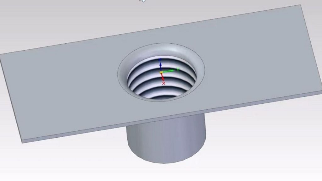
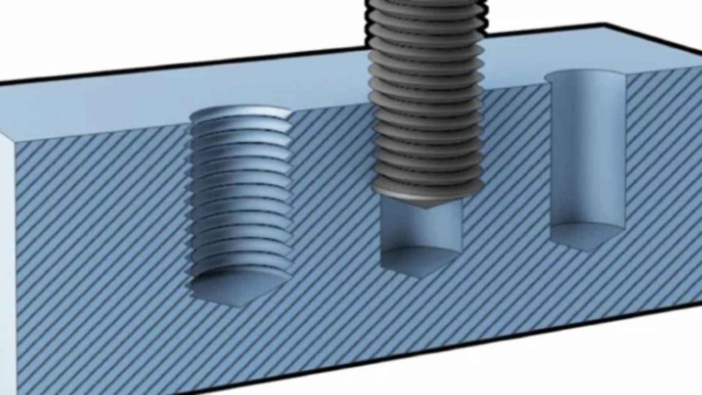
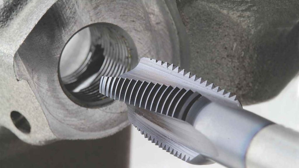
A tapped hole has its internal walls threaded for bolt insertion. These holes accept bolts directly without requiring a nut on the opposite side. The other side of this hole requires no nut.
Thread depth matters here. The required amount of engagement must be sufficient to maintain hardware retention. It is important to choose taps according to thread specifications. These holes are most frequently used in machined housings and mounts.
The threading becomes insufficient when you tap at a shallow depth because the bolts will start to pull out. The part becomes weakened when you tap it to a depth that exceeds its requirements. You should use thread calculators to determine the correct thread dimensions.
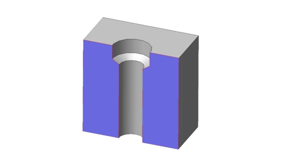
The design of a blind hole ends without cutting through completely. The drilling operation reaches its stop point at an exact depth. The concealment of fasteners can be achieved through the use of blind holes.
Moreover, using blind holes helps maintain part cleanliness and safety. Such holes serve to prevent leakage when operating under high pressure conditions. Blind holes are regularly used in castings and motor housings.
How to produce these holes? To create blind holes, you need complete management of depth measurement. The drilling technique of peck drilling integrated with depth stops, should be used. Closely observe the tool to prevent hitting the bottom because this could lead to tool damage.
A through hole extends from one side to the other side of the part. Inserting fasteners becomes possible from both sides of the part. Through holes produce effective outcomes in situations where you can achieve complete access to the workpiece.
On the application side, through holes serve best when used with bolts and pins. These appear within structural plates and are also present in gearboxes. Drilling and inspection of through holes prove simple for both operations.
The holes can be reamed to meet specifications for dowel usage. Due to this approach, the results deliver high precision with repeatable measurements. The fit will be compromised by any burrs located near hole openings.

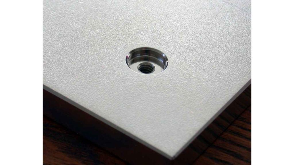
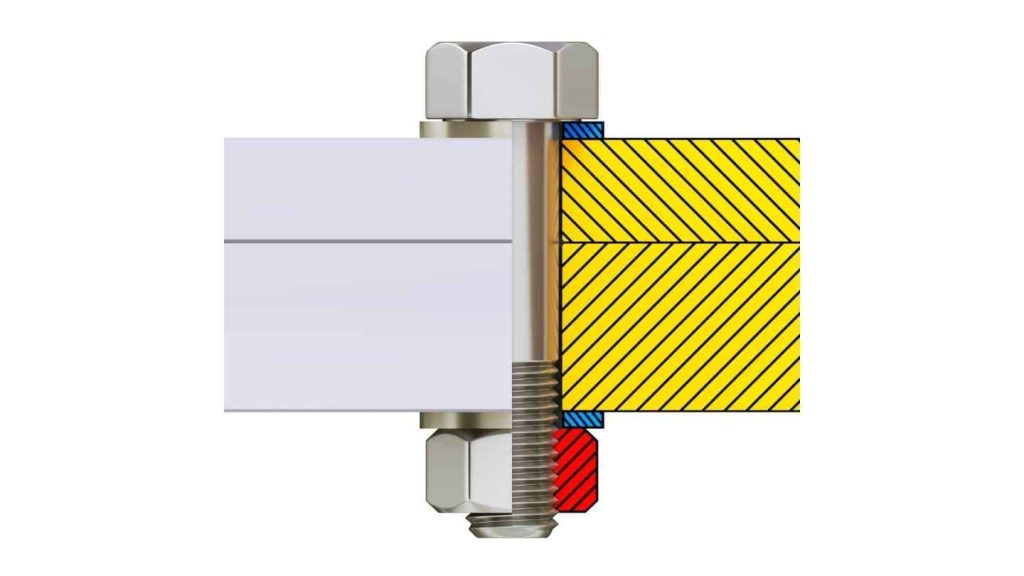
By producing a flat-bottomed recess, a counterbore performs its function. The counterbored area allows bolts to rest at the same level. Making a bigger hole diameter over a smaller one forms a counterbore.
These holes serve to create neat and compact assembly designs. In general, counterbores are used in clamp assemblies and brackets. Check that the bolt head extends beyond the hole by its total diameter.
You must use socket head cap screws alongwith counterbores. The components reach a better seat position while improving clamping strength. Counterbores possess distinct functions from spotfaces because they produce flat-bottomed recesses.
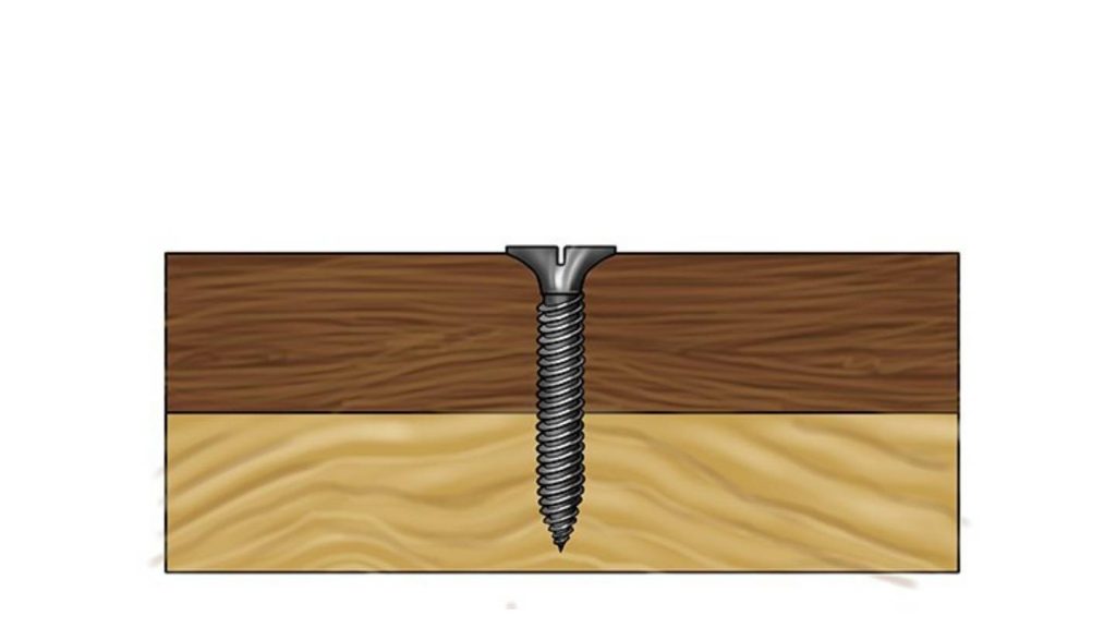
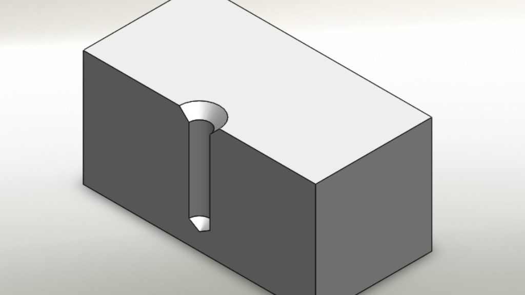
A countersink shapes the material with a conical hole. The equipment creates a conical depression which mainly serves flat-head screws. The screw extends until it reaches full surface compatibility with the part structure.
The formation of a conical recess using countersinks helps minimize edges and potential snag points. The tool can be found in sheet metal and tool handles. Select an appropriate angle which corresponds to the screw type.
Common angles include 82°, 90°, and 100°. Drill-and-countersink tools combine multiple functions, and these save steps during machining.
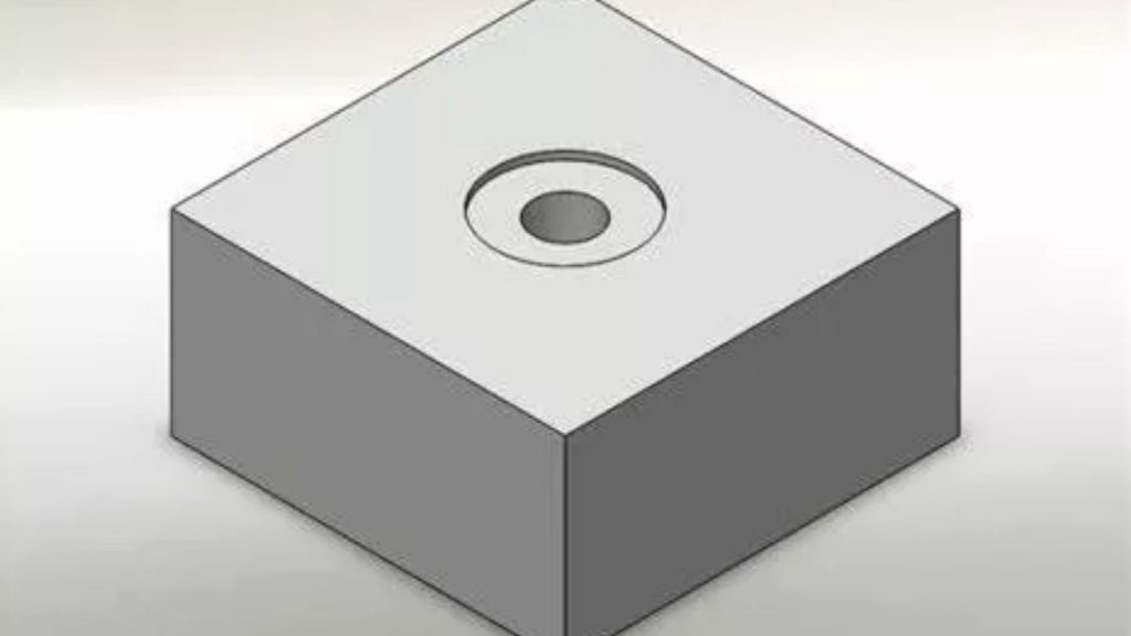
You can use a spotface hole to flatten out surface irregularities to create a proper seating area for bolt heads. The cut requires precision along with a shallowness in depth.
Spotfaces operate without affecting the operational feature of the hole. These modifications affect only the quality of the fastener interface. Spotfaces should be used on both cast materials and rough stock sections.
Create a spotface with a diameter slightly larger than the bolt head. This will ensure a better fit. The mounting pad becomes weaker when you extend the spotface size beyond its necessary dimensions. Therefore, you must always control the depth tightly.
Dowel holes are used to secure two different parts together. A pin that requires press-fitting serves to maintain the precise alignment. The joining method depends on interference principles inside tight dimensions.
You need to achieve high precision when drilling dowel holes. The required position and exact diameter make up a critical specification. You can use dowels as elements in jigs, molds, and locating features.
In addition, use reamers for tight dowel fits. Drill both parts together when possible. That ensures exact alignment and easy pin insertion.
A screw clearance hole functions as a threaded bolt opening. The holes serve the same purpose as bolt clearances by matching screw thread profiles. Screws require one part to pass through without any disruptions.
The threaded opening allows the threads from the other piece to clamp into place. The hole diameter must match exactly with the screw shank dimensions. The thread grip and appropriate clamping function can be achieved through these holes.
The hole size needs to be appropriate because any small size may result in part splitting. Aside from this, the hole dimension also needs to be optimum for thread retention; otherwise, failure can occur. Designers should use screw clearance charts as a reference.
Thread relief holes create an additional space for material removal outside of threads. The purpose of thread relief holes is to stop the tap from damaging materials. The additional space provides better tool clearance.
A relief cut must be applied to deep thread-shaped holes to function properly. The feature safeguards the thread structures and extends tool operational durations.
You can manufacture reliefs by implementing undercuts. These make the thread run out smoothly. Moreover, using reliefs helps both extend tool life and improve the operational duration of manufactured parts.
The modern CAD systems present complete hole specifications to their users. The system requests you to establish the type, depth, angle, and diameter of your holes. Hole callouts guide the designers to ensure optimal functionality. These encompass thread specs and fit tolerances.
The information about holes within the CAM system generates production paths for tools. Drills, taps, and mills operate independently. CAM tools automatically produce spotfaces and countersinks during the manufacturing process. It reduces errors that could appear during actual production.
Every hole in your design model must receive a complete feature specification. The shop obtains faster programming capabilities, and all the necessary hole information must be in line, and clear to avoid manufacturing flaws. A Clear design speeds up production.
The implementation of parametric hole features in CAD software diminishes the occurrence of errors. Standard hole templates allow you to establish libraries for common hole programming.
There exist multiple approaches to making holes. CNC Drilling stands as the finest hole-making technique. The material gets penetrated using twist drills. Tapping adds threads. While Boring improves size and finish.
Special tools enable the production of counterbores and countersinks. The production of spotfaces requires using facing cutters or end mills. Every tool requires matching dimensions to match specific hole requirements.
When creating dowels, reamers help you maintain refined quality. The speeds, depths, and feed rates are critical parameters in designing perfect holes.
High-speed machining reduces cycle times. Peck drilling functions as a method to evacuate chips from deep drilling holes. Last but not least, select appropriate cooling systems and tool covering materials.
Professionals regularly overlook actual production problems during their work process. The selected holes remain inaccessible to tooling instruments. Or they stack tolerances wrong.
Misaligned holes ruin assemblies. Undersized holes break taps. Sharp hole edges invite cracks. Always check tool access and fit tolerances. Simulate the assembly whenever possible.
Do not combine imperial units with metric units in your designs. Your hole dimensions should have a simple and uniform setup. All shop errors and time delays are eliminated through this practice.
Holes require enough distance between their edges and the material boundary. When holes are positioned too near to part edges, they are likely to develop cracks. Digital mockup verification needs to be performed for all hole layouts.
The appearance of holes being easy conceals their complexity. The different types of holes need specific reasons alongside their associated methods for execution. A well-chosen hole type helps maintain optimum functionality and component or assembly performance. The proper choice of holes allows quicker production and fewer hours on the machine tools.
Your study of fundamental hole types reaches a total of 12 types in this blog. The lesson has explained their operational principles and their significance. Use this knowledge to create holes in your following design.
Effective engineering practice entails designing smart holes. The manufacturing process, starting from CAD through CAM to the shop floor, is directed by holes. Complete mastery of holes delivers mastery in mechanical design.

Brass Vs Copper for CNC Machining: Which Material Is Best

CNC Plastic Machining: Plastic Selection, Machining Processes & Key Applications

A Complete Guide to Aluminum Sheet Metal Fabrication

Deep Hole Drilling: What It Is & How It Is Done?

Rapid Prototyping: All About Process, Techniques, Pros & Challenges & More

All-Inclusive Guide to Laser Cutting Aluminum