
Tolerances are the DNA of designs that may become manufactured, the measured limits of permissible change that mend the gap between intended design engineering and real objects. In the absence of systematic tolerance standards, interchangeable parts, dependable assemblies, and mass production are doomed; Anything, even a little bit bigger: a strangely enlarged shaft or a groove hole that is slightly out of position in a mounting spills over into fit failures, accelerated wear, safety risks, and expensive rework costs. ISO systems such as ISO 2768 and 286, and Geometric Dimensioning and Tolerancing (GD&T) offer the much-needed framework to define, convey, and confirm such limits. The ISO 2768 simplifies non-important dimensions, the ISO 286 regulates the precision of the cylindrical fit, and the GD&T has General Control of forms, orientation, and location that do not refer to linear measurement. Collectively, they are the pillars of design-for-manufacturing (DFM); its members can work together across international supply chains, balancing accuracy against cheaper prices.
Before diving into the details of the standards, it is vital to understand the importance of tolerances. Any production process contains variability as a result of tool wear, temperature changes, vibration, material disparity, and the degree of measurement uncertainty. Tolerances define the allowable zone for this variation.
The Cost-Precision Paradox: Greater tolerances take exponentially more money. Even standard CNC calls for 3-5x longer cycle times than IT11 (0.16mm) to achieve IT6-grade precision (0.019mm on a 50mm shaft) with grinding/polishing and specialized metrology. A McKinsey study revealed that part costs are inflated by 30-200 percent by unnecessarily restrictive tolerances in the automotive and aerospace industries.
Tolerances: Functional vs Cosmetic:
Functional: It is essential to performance (e.g., bearing fits, sealing surfaces).
Cosmetic/Aesthetic: Would affect only perception and not mechanics (gaps on the outer casing). One widespread cost driver is the misclassification of cosmetic features as functional.
The ISO 2768 addresses the problem of over-specification that has permeated engineering design drawings. Before its acceptance, engineers endured cumbersome, time-consuming exercises by tolerating every little dimension, 70 percent of which were inoperative. This led to drawing congestion, unpredictability of the suppliers, and excessive expenses due to unwarranted accuracy. The typical practice resolves it by setting universal default tolerance classes (f/m/c/v for linear d; H/K/L for geometrical features). For example, the annotation of a title block ISO 2768-mK automatically assigns a +/- 0.8 mm tolerance to a 100mm untoleranced length (Class m) and 0.4 mm deviation flatness (Class K), and can override critical features. ISO 2768 reduces drafting time by 50 percent through streamlining documentation and synchronizing global supply chains, and cutting manufacturing costs by 25 to 40 percent for non-critical parts such as structural weldments or housings in consumer products.

The ISO 2768 comes in two complementary sections discussing standard dimensioning requirements:
Part 1 ( ISO 2768-1): Linear and angular measures (Measurements of lengths, diameters, chamfers, angles).
Part 2 (ISO 2768-2): Geometrical tolerances(flatness, straightness, perpendicularity, symmetry).
There exist four tolerance classes for ISO 2768-1 that are indicative of stringency:
ISO 2768-2 Tolerance Classes:
Some Examples of Linear Tolerances ( ISO 2768-1 Class m ):
| Nominal Size (mm) | Tolerance ±(mm) |
| 0.5 – 3 | 0.2 |
| 3 – 6 | 0.3 |
| 6 – 30 | 0.5 |
| 30 – 120 | 0.8 |
Some examples of Geometric Tolerances (ISO 2768-2, Class K)
| Feature | Tolerance (mm) |
| Flatness (≤100mm) | 0.4 |
| Perpendicularity | 0.6 |
ISO 286 was developed to address the part incompatibility crisis in assembly before the Industrial Revolution. In the past, a 50 mm shaft from a single supplier may not be compatible with a 50 mm hole from a second supplier because of disparate tolerance areas, hence the necessity of hand matching, which is very expensive. This standard mathematically ensures interchangeability in two pillars: tolerance grades (IT01 to T18), which are used to quantify precision (e.g., IT6 = +/- 0.019 mm in a 50 mm shaft), and basic deviations (letters such as H or g) that locate the tolerance regions about nominal size. As an example, the clearance between an H7 and g6 hole-shaft is predictable: the hole (e.g, 50+0.025) is always greater than the shaft (50-0.025). This system supports mass production of engines, bearings, and gears, enabling a gear machined in Germany to fit snugly on a housing made in Japan without selective assembly, which is the basis of automated manufacturing.

The International Tolerance grades (IT01 to IT18) defined in ISO 286 represent 18 International Tolerance grades, with lower numbers representing higher precision. Key grades:
IT6-IT7: High Precision (bearings, aerospace)
IT8-IT9: General Machinery (gears, pumps)
IT10-IT11: Press-fit Components and rough castings
IT12–IT14: Semi-Finished Products and Rough Machining
IT15–IT16: Structural Engineering and Heavy Industry
IT17–IT18: Very Coarse Fabrication
Tolerance Values for IT Grades (mm, Ø50mm Example):
| Grade | Tolerance | Process |
| IT6 | ±0.019 | Grinding/Honing |
| IT8 | ±0.039 | CNC Turning/Milling |
| IT11 | ±0.160 | Casting/Forging |
The tolerance zone is set about the nominal size by use of letters:
Uppercase (Holes): H = Zero line at LMC (Least Material Condition).
Lowercase (Shafts): h = Zero line at MMC (Maximum Material Condition).
Fit Categories:
RealWorld Fit calculation:
There must be a hydraulic piston ( 40mm) with a minimal amount of leakage:
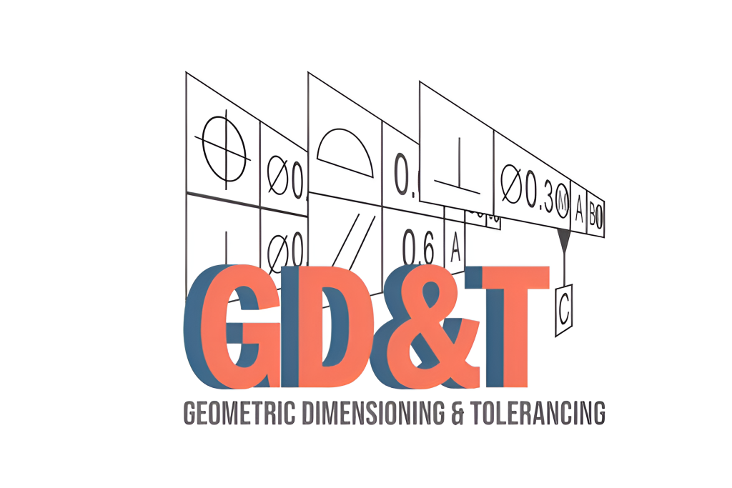
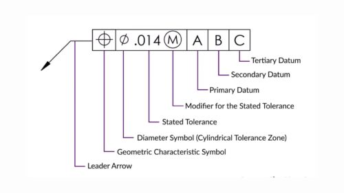
Geometric Dimensioning and Tolerancing (GD&T) addresses the fundamental defect of linear tolerancing in the past: it is incapable of assuring functional assemblability. Although linear tolerances regulate size, they do not affect geometry- they can therefore produce 'paper-correct components' that perform badly in the real world (e.g., tolerances on the height of a seal plane of a pad with adequate height variation, but which bends and thus leaks). Let GD&T eliminate this using symbolic controls (e.g,. 250 flatness, 250 position) defined in a Datum Reference Frame (DRF) to refer tolerances to a practical interface between different parts (such as a mounting surface). As an example, the use of a position tolerance of ⌖ 0.2 mm ʜ to bolt holes requires that the pattern of the holes lies within a cylindrical area relative to datums, with 0.2 millimetres extra tolerance over what would be physically present as the holes are not in the most favourable position (maximum material condition). This method reduces cycle cutoffs of assembly failures by 63 percent in the aerospace industry and costs by 30 percent compared to coordinate tolerancing, hence making GD&T an unavoidable element to high-risk interfaces such as turbine blade roots or medical implant joints.
This language is a symbolic embodiment of the GD&T controls, including form, orientation, location, and runout, with datums as a base of reference.
Core Controls:
Datum Reference Frame (DRF): Datum reference frame is a coordinate system founded on features of functional parts:
Modifiers:
Traditional Linear:
GD&T Position Control:
Example: Four M8 mounting holes:
Determine important boundaries:
| Tolerance Grade | Process | Surface Finish (Ra) |
| IT5-IT6 | Grinding/Lapping | ≤ 0.4 µm |
| IT7-IT8 | CNC Machining | 0.8 – 3.2 µm |
| IT9-IT11 | Casting/Forging | 6.3 – 25 µm |

Such tolerancing has wide application in various industries, each serving the purpose of maintaining the quality of a part and assembly.
Applied to systems that do not have critical functions in which wide margins are acceptable:
General machined Parts: brackets, plain housings, covers.
Sheet Metal: length and width, bending angles.
Welded Structures: Dimension overall and angularity
Early Design: Prototypes focusing on overall form
Used in those areas where cylindrical features are important:
Bearings and Shafts: Clearances or Interferences.
Pins and Holes: Ensuring whether one will slide freely or press fit.
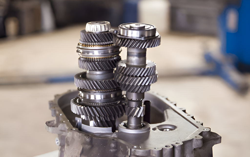
Gear Assemblies: Assembly of a gear fitted to the shaft.
Tools and Fixtures: To have accurate fitting components, such as dowel pins.
Used to provide features with exact functional and dimensional control
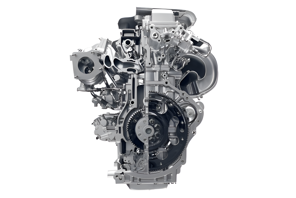
Automobile: Engine units, transmissions, chassis parts to align and perform.
Aerospace: Structure of aircraft, components of engines, which have to be built with extreme accuracy and safety.
Medical Devices: Medical equipment - surgery instruments, implants, prosthetics, etc., of vital functionality and interface with man.
Precision Machinery: Robotics, machine tools, precision, and machine tools with accuracy and repeatability of motion.
Consumer Electronics: Complex enclosures, internal mounting features for miniaturization, and reliable assembly.

Effective design with limits requires understanding functional needs, manufacturing capabilities, and cost implications for each guideline.
Tolerance Has to Be Functional: Where it is important to use close tolerances, otherwise, tolerances should not be overdone.
Manufacturing Capability: Design within Manufacturing processes whose precision you have chosen that is within the bounds of reality.
Cost Consideration: Stricter limits result in higher costs; strive to use the largest possible tolerance that still satisfies the functional requirements.
Material Properties: Account for material behavior, thermal expansion, or moisture absorption.
Inspection Feasibility: Design components that support easy and precise measurement of toleranced features.
Default Use: Apply to all dimensions and manufacturing features without definite, separate allowable deviations.
State Class: The tolerance class selected (e.g., ISO 2768-mK) must be clearly defined on the drawing.
Avoid Conflicts: Do not apply to features that are covered by a defined dimensional or GD&T tolerance.
Mating Cylindrical Features: Can be used to mate shafts and holes with a given clearance, as well as transition and interference fits..
Select IT Grade: Select worldwide Tolerance (IT) grade (e.g., IT6 grade, precision requirement, IT10 grade, not critical).
Select Fundamental Deviation: The Hole (e.g., H) and Shaft (e.g., g) fundamental deviation should be selected to obtain the desired fit.
Specify Clearly: The basic size and fit (as an example, 20H7/g6) should be specified on the drawing.
Functional Prioritization: Identify essential functional factors to determine functional and assembly under GD&T.
Seat Datums: Three features should be chosen that are mutually orthogonal as datum features to create a working datum system for the part.
Apply Feature Control Frames: Use Frames of control features with dimensional characteristic symbols, tolerance values, and datum references with important features.
Consider Modifiers: Acquire material condition modifiers (e.g., MMC) when justified to provide the best processing of materials.
Control Categories: Apply GD&T controls under the categories of Form, Orientation, Location, Profile, and Runout to specify definite dimensional needs.
GD&T sorts the geometric features into five broad types to specify specific functional control:
Control the form of individual features, regardless of their orientation or position.
Flatness: the flatness of a surface.
Straightness: The degree of straightness that a line element has.
Circularity (Roundness): Roundness of a circle feature.
Cylindricity: The degree of cylindricity of a feature, i.e., the combination of straightness and circularity.
Angular control of the feature to datum features.
Perpendicularity: Of a feature to a datum: The extent to which a feature is perpendicular to a datum.
Parallelism: The parallelism of a feature to a datum.
Angularity: The angle of an attribute about a reference.
Regulate the locating of a feature to datum features.
Position (True Position): Sets a region of tolerance for a feature's center relative to its ideal theoretical place against the datums.
Concentricity/Symmetry: Exercise coaxiality/symmetry (rather rare, frequently under Position).
Exercise control of the profile (outline) of a surface or a line, or a combination, including form, orientation, and location.
Profile of a Line: State the form of a cut.
Profile of a Surface: Controls the three-dimensional geometry of a complete surface.
The variable is the assemblage of a surface of revolution as the portion rotates about its datum axis.
Circular Runout: Regulates circular runout of a cross-section.
Total Runout: Regulates runout of an entire surface.
Modern fabrication relies heavily on accurate tolerance standards to ensure quality, functionality, and cost-efficiency. Standards like ISO 2768, ISO 286, and GD&T provide a solid framework for controlling dimensional variation across production. ISO 2768 sets general tolerance limits, ISO 286 focuses on fits and cylindrical features, and GD&T allows for precise communication of functional geometry. While each standard is powerful on its own, mastering them together ensures better alignment between design, manufacturing, and inspection. At ApexRapid, we apply these standards in our precision CNC machining services to help clients achieve consistent, high-quality results—on time and within spec.
A1: The traditional +/- tolerancing is a square tolerance zone to control size. GD&T geometry coordinates (form, orientation, location) along functional lines, and frequently permits the enlarging of limits of both cylindrical and non-cylindrical shapes.
A2: For non-critical features that have acceptable broad limits, use ISO 2768. Apply GD&T when extreme tolerance control is imposed on critical features to control fit, form, or assembly
A3: ISO 286 provides standardization of fits to cylindrical features (holes/shafts), ensuring that when components with the same specification are produced, they fit together, irrespective of which supplier they are ordered from, to give switchability.
A4: Yes, it's usual practice. GD&T for critical features, ISO 286 for specific fits, and ISO 2768 for all remaining, non-explicitly toleranced dimensions to streamline the drawing.
A5: No, not always. Toggle press toleration is more expensive when it is tighter. An efficient part satisfies functional requirements; in other words, a part that satisfies functional requirements is better. Use the most indulgent tolerance that assures performance without incurring unneeded expenses by over-tolerating.
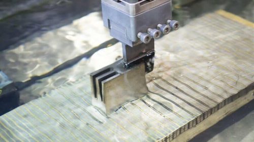
How to Get Accurate and Consistent Tolerances with Wire EDM
An Ultimate Guide To Aluminum Extrusion
GD&T Basics: How to Make Accurate Engineering Drawings
A Complete Walkthrough To CNC Chamfering
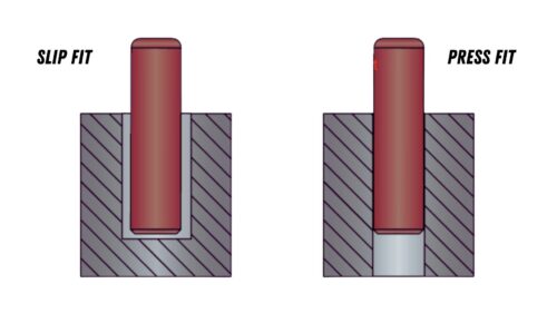
Press Fit Vs Slip Fit: A Breakdown of the Difference
Taps For Threads: Their Common Types