
In CNC machining, precision goes beyond dimensional accuracy—surface texture plays a vital role in a part’s performance, durability, and appearance. Even surfaces that appear smooth may have microscopic peaks and valleys. Controlling surface roughness is essential for engineers and machinists, as it affects friction, wear, fatigue, sealing, coating adhesion, and conductivity. This article explores key surface roughness indicators, their impact on CNC quality, and how design and finishing processes influence final part performance.
Surface roughness can be differentiated from surface waviness (larger-spaced variations) and form error (shape deviation resulting from overall). Surface roughness is a finer unevenness that occurs as a result of the production process. It is the set of points of proximity to the peaks and valleys of the real surface topography with an ideal, dreamy, smooth plane. Such deviations are caused by the cutting tool on the workpiece material during machining actions, such as turning, milling, drilling, or grinding. Factors such as tool geometry, feed rate, cutting speed, depth of cut, tool wear, vibration, the use of coolant, and even the natural characteristics of the material to be machined (e.g., hardness, the grain structure) all deposit their mark on the surface texture. This texture can be measured objectively, communicated, and controlled by quantification of the functional textural aspects of the surface.
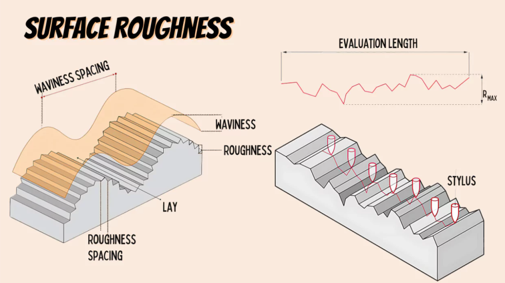
An overall look may result in an approximate estimation, but a quantitative measurement will necessitate standard parameters. Some of the indicators are employed, and each of them provides a distinct vision of the surface profile:
The most widely used and standard surface roughness parameter is Ra by a lot. It is defined as the arithmetic mean of the absolute values of the heights of the profile (peaks, valleys) differences with the mean line computed on a given length of evaluation. In essence, it provides a single numerical characterization of the total height variation of the surface irregularities over the sampling length. The smaller the Ra, the smoother the surface, and the greater the Ra, the rougher the surface. Consider an example of a precision bearing raceway that would need an Ra of 0.2 m, whereas a non-critical structural component would have an Ra of 6.3 m. Its low cost and good performance in describing general surface texture make this parameter commonly used in most specifications.
Whereas Ra gives an average, Rz centers on the extremes in the same sampling length. It can be described as a sum of profile peak height (Rp) of the highest profile and profile depth (Rv) of the largest profile in the distance. Rz provides a better image of the peak-to-valley variation at the maximum over a rather small range. For applications in which the deepest valleys or highest peaks are important (e.g., in sealing a surface (where a deep valley may cause a leak) or in fatigue-sensitive applications (where a sharp peak may act as a stress concentrator, starting a crack)), this parameter is more important. Rz values are also greater than those of Ra on the same surface.
Rq or RMS roughness is the root mean square arithmetic mean of the differences between the profile height and the mean line, over the length to which the measurements are being considered. Mathematically, one squares the deviations, averages these squares, and obtains the square root. The lower the value, the higher the sensitivity to large deviations (peaks or valleys) by Rq than Ra. Each perfectly random Gaussian surface profile has an Rq and Ra difference of 11 % with the value of Rq being greater. Although not as frequently stated as Ra in general machining, Rq is employed extensively in optical applications, tribology studies, and in any case where the surface height statistical distribution is considered.
To standardize roughness and specification, the International Organization for Standardization (ISO) has a system of grades of roughness, usually indicated with the letter N followed by a number (e.g., N1, N5, or N10). Such grades can be matched to ranges of Ra and Rz values. It is of high importance to be familiar with this continuum to make the right choice of finish for an application.
N1 (Ra ≤ 0.025µm) is very smooth and must be polished or lapped frequently. N1-N3 surfaces (Ra ≤ 0.4 µm) have low peaks, and there are changes in valleys. Examples of applications requiring such ultra-fine finishes include precision optical parts (lenses & mirrors), high-pressure hydraulic gaskets and valves, critical bearing surfaces in aerospace equipment or medical devices, wafer fabrication equipment, and surfaces where ultra-high vacuum is required. The attainment and retention of these finishes are both complicated and expensive, and require very tight control of the process, top-quality tooling, and frequently, numerous finishing steps.
The N4 (Ra=0.8 or less micrometer (μm)) to N6 (Ra = 3.2 or less μm) are fine finishes. They are smoother than normal as-machine surfaces, but cost less to make than mirror polishing. They are obtained through precise machining with sharp tools and ideal parameters (lower feeds & high speeds), and possibly light grinding or honing. There is extensive and vital use in applications including bearing surfaces in general machinery, sliding surfaces, hydraulic pistons and cylinders, pump parts, gears needing good meshing and wear properties, and components subject to moderate fatigue loads. Such an area of composition offers the optimum combination of increased functional performance (low friction, good wear resistance, good fatigue life) at a minimum cost of manufacture of many precision components.
Medium Finishes (N7 - N9): The Workhorse Range
Fine range (N7 (Ra ≤ 6.3 µm) to N9 (Ra ≤ 25 µm) is commonly referred to as standard or commercial. These are the surfaces that you would obtain as a result of conventional machining, CNC operations (milling, turning) under normal conditions with average tool sharpness. The marks of visual machining are normally evident. Such a finish is more than sufficient in many product types, where cosmetics are a secondary consideration and absolute surface performance is not a necessary consideration. Examples include non-sealing static faces, internal structural casting, shafts and housings where bearings or seals are pressed onto a separate surface, and brackets, mounting plates, and most parts in consumer items that do not need a cosmetic finish. It is the most economical alternative to smooth working components, whereby extreme smoothness is not worth it.
Samples that fall under the N10 (Ra ≤ 50 µm) to N12 (Ra ≤ 200 µm) range appear visibly rough, and their tool marks are deep as well as the peaks and valleys. As such, these are usually caused by coarse machining processes that have a high material removal rate, such as with high feed rates, deep cuts, or dull tools. They could also be deliberate for certain purposes. Applied Use Respecialised areas: surfaces to which paint or coating adhesion is critical (the roughness gives it tooth), surfaces to which oil retention is necessary (lubrication), surfaces to be used as a heat sink (greater available surface area), seating surfaces of some types of gaskets (depending on the type of gasket), and in non-crucial structural members, where the condition of the surface needs no functional consideration. The level of aesthetics is not good.
For a target surface roughness, there are many factors other than the choice of a CNC Machine.
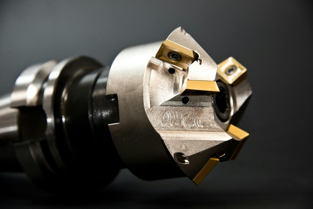
The most important is the tool nose radius. The greater the radius, the smoother the finish will be, as the tool will be able to wipe more surfaces. Tool form and angles, rake angles, clearance angles, and tool sharpness (wear) have a significant influence on chip formation and surface generation. A blunt tool rips through material instead of shearing it off with a smooth edge, and this raises roughness.
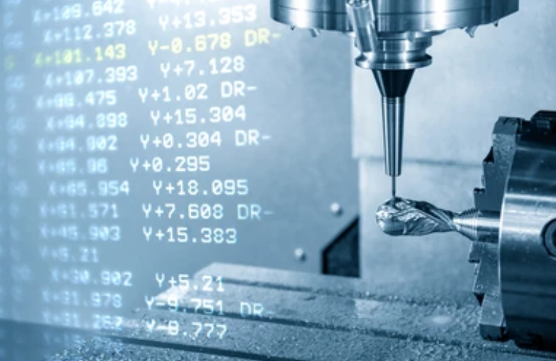
Feed rate is the most dominant instantaneous factor- The higher the feed rate, the higher the roughness tends to be. Closely related to the depth of cut, which is related proportionally to roughness. The speed of cut (surface feet per minute or meters per minute) is also a factor; low extremes can lead to rubbing or built-up edge, and high extremes can cause vibration or become hot. Material and tooling optimize the speed. The depth of cut tends to interact with feed and speed, but not affect them as directly.
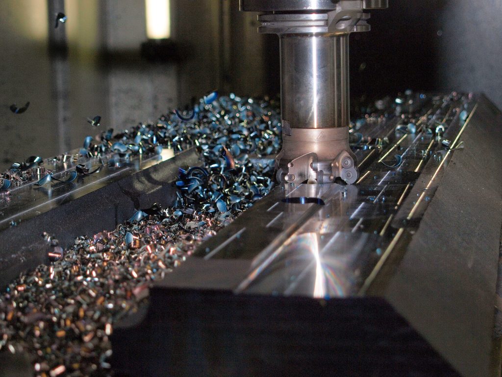
Undesirable vibration of machine tool, workpiece, or toolholder during the cutting process forms characteristic chatter patterns in front of the surface, which vastly accentuates the roughness. To counter chatter, it is vital to use stiffer setups, balanced tools, optimum speeds and feeds, and in some cases, dampening systems.
The properties of materials, with factors such as homogeneity, hardness, and ductility, influence the machinability. The tougher materials are usually cut less easily but allow smoother finishes. The ductile materials may result in the formation of built-up edges when the parameters are not met. Tool wear is accelerated by abrasive materials, leading to a poor finish. The final texture may also be affected by the grain structure of castings or forgings.
The proper application of the correct coolant reduces heat and abrasion of the tool, prevents the formation of a built-up edge, and assists in flushing away chips that then may scratch the machined surface. Poor coolant tends to give low finishes.

The workpiece clamping should be secure and rigid to ensure that no movement or vibration occurs during the cutting process.
The basic Fourier Cantor's roughness levels are achieved by the primary machining (roughness forming) processes, and to attain narrower grades, particular finishing is used:
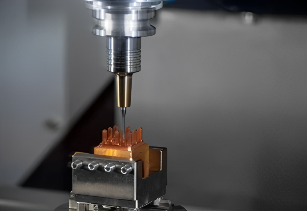
More often than not, the least expensive finish improvement is machining optimization, i.e., sharper tool utilization, enlargement of the tool nose radius, slower feed, fast cutting (not too fast), undersized depth of cut, improved rigidity, and proper coolant flow. With high-speed machining (HSM) techniques, fine finishes can be achieved.
Grinding involves contacting a material by an abrasive process through a spinning wheel. It is one of the best used to produce fine (N4-N6) and mirror (N1-N3) finishes on hardened materials. Bearing races, precision shafts, and tooling are done through precision grinding, cylindrical, surface, and centerless grinding.

Generates a typical cross-hatch pattern by use of abrasive stones of controlled pressure and motion (rotary and oscillatory). Superb to obtain fine finishes (N5-N7 zone) and enhance geometric precision (e.g., roundness, straightness) in the bore, including engine cylinders, hydraulic tubes, and bearing housings. It is excellent in grinding lay and micro-burr removal.
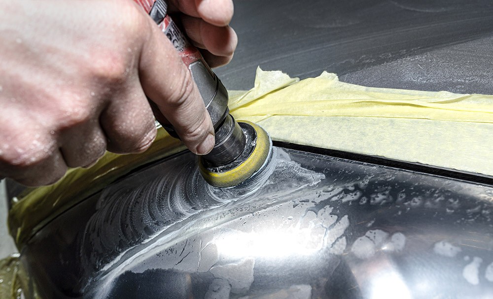
Abrasion with successively finer substances (usually on gentler laps) to attain the slickest mirror completes (N1-N3). Polishing is a manual and semi-automated process, whereas lapping requires a tool (lap) that follows the surface of the workpiece. The application includes optical components, surface sealing where super-low leakage is essential, and other surfaces where low friction or adhesion is necessary.
Extrudes or strikes a viscous abrasive-filled polymer medium through or across the workpiece surface against pressure. It is best used to deburr and smooth complex internal passages, cavities, and hard-to-reach surfaces, improve Ra, and eliminate stress risers.
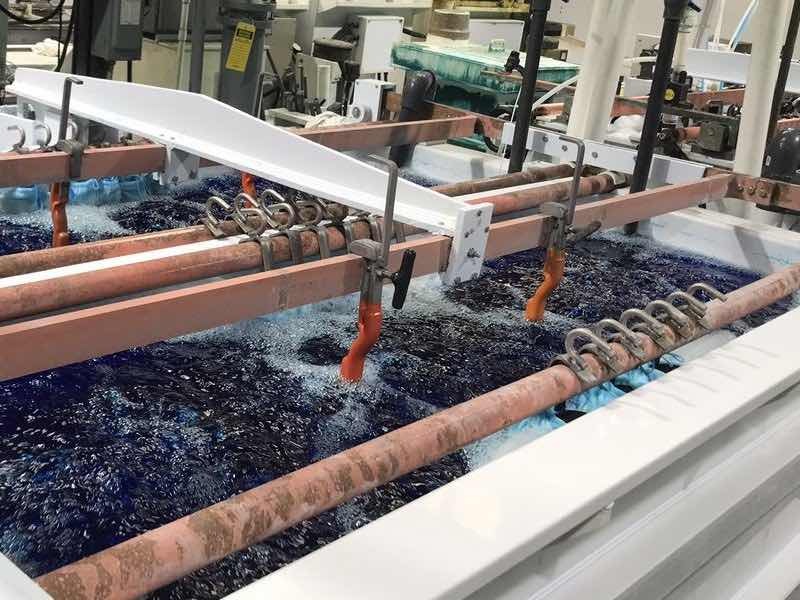
An anodic process of dissolving surface material via an electrochemical process, removing microscopic peaks, leaving a smoother, brighter surface that is also corrosion resistant. Useful in finishes on the complex geometries (both internally and externally), stainless steel parts, and medical implants. Produces finishes as fine as mirrors.
Mass finishing is a process in which parts are placed in a rotating barrel or vibratory tub filled with abrasive medium and compounds. Usage primarily working as a deburring, edge rounding, and surface appearance (cosmetic finishes) finishing operation, where often moving parts in medium/coarse to a more standard medium/fine range, however, with less precision control than with other techniques.
Even the surface roughness needs can differ tremendously depending on the application:
Aerial Vehicle: Turbine blades (fine / mirror airflow), bearing races (mirror), hydraulic actuators (fine), structural parts (medium). Fatigue life and performance are critical.

Automotive Engine cylinders (honing - fine), crankshaft journals (grinding - fine/mirror), gear teeth (fine/medium), body panels (medium to paint), brake discs (medium/fine). Influences on wearing, effectiveness, and noise.
Medical Implants & Instruments: implants (mirror/polished to be sure of biocompatibility/wear), surgery instruments (fine/mirror to have cleanliness and corrosion), dental parts (fine/mirror). Of prime importance to biocompatibility and avoiding infection.
Fluid Power: Hydraulic/pneumatic valves and pistons (fine/mirror seal), pump housings (fine/Medium), manifolds (Medium/ fine). Necessary for avoiding leakage and efficiency.
Electronics: heat sinks (coarse or medium surface area), connector pins (fine contacts), semiconductor wafer handling (Reflection to guard against contamination).
Consumer Goods: Appliance cases (paint surface), camera camera camera lens barrels (fine), watch cases (reflective, fine to high), handles (medium).
Surface roughness is more than a cosmetic detail—it's a critical engineering factor that directly influences a part’s performance, reliability, and longevity. Key roughness parameters like Ra (average roughness), Rz (peak-to-valley height), and Rq (root mean square roughness) help define surface quality in measurable terms. Understanding these values, along with standard roughness grades from super-smooth N1 to coarse N12, allows engineers to align surface finish with functional requirements.
While achieving finer finishes can enhance part performance, it also introduces higher costs and processing complexity. That’s why it's essential to strike a balance between functionality, manufacturability, and cost during the design stage. At ApexRapid, we apply our CNC machining expertise to help clients achieve consistent surface finishes that meet both tolerance and application demands—ensuring every part not only looks right, but performs right.
A: Ra is a single-value average that is simple and concise and can provide the overall variation of height of surface irregularities in the measured profile. It is highly correlated with most functional parameters, such as friction and wear across a variety of surfaces, and is easy to measure and interpret.
A: Experienced machinists are often able to detect visually the difference between very rough and very smooth surfaces; however, quantification of these differences cannot be made by eye. It is possible to have two surfaces sharing the same Ra value but assessed as visually different, because they have been machined in differently (turning vs. grinding). Visual comparison standards are well known, but accurate magnification needs a profilometer.
A: Employ the indicated symbols as outlined by ISO standards of surface texture. The simplest check mark is the most common one. Write the value ( e.g., Ra 0.8, or N6 ) beside the symbol. This symbol is drawn on the surface line, leader to surface, or at the part outline near the surface.
A: That is based on the application. Ra is superb in general characterisation. Rz plays an important role when the largest valley or sharpest peak is a limiting factor, e.g,. sealing integrity (leak paths) or fatigue strength (stress concentration at sharpness). Both are often defined for critical use.
A: The microscopic stress concentration occurs at surface roughness tips. When the loading is cyclic, the cracks will tend to work up the peaks first. By reducing surface roughness values such as Ra and Rz, stress concentration is minimized, thereby enhancing a component’s resistance to fatigue failure.

Rapid Prototyping: All About Process, Techniques, Pros & Challenges & More

All-Inclusive Guide to Laser Cutting Aluminum

CNC Gear Cutting: Process, Techniques & Effective Strategies

Laser Welding: Process, Effective Tips & Techniques for Optimal Welds

Metal Stamping Design: Process, Considerations & Useful Tips

Aluminum Heat Sinks: Process, Techniques & Applications