Geometric Dimensioning and Tolerancing (GD&T) is a standard method for defining part features on engineering drawings. It helps you communicate exactly how parts should fit and function. Instead of relying on vague notes or rough sketches, you give precise instructions that everyone can follow.
You use GD&T to describe things like
These details are critical when parts need to perform together without failure. It’s especially useful when different teams and suppliers are involved in the same project.
With GD&T, you reduce errors, speed up production, and avoid costly rework. You only control what matters, which means fewer tight tolerances and less wasted time. That makes your drawings easier to build from and inspect against.
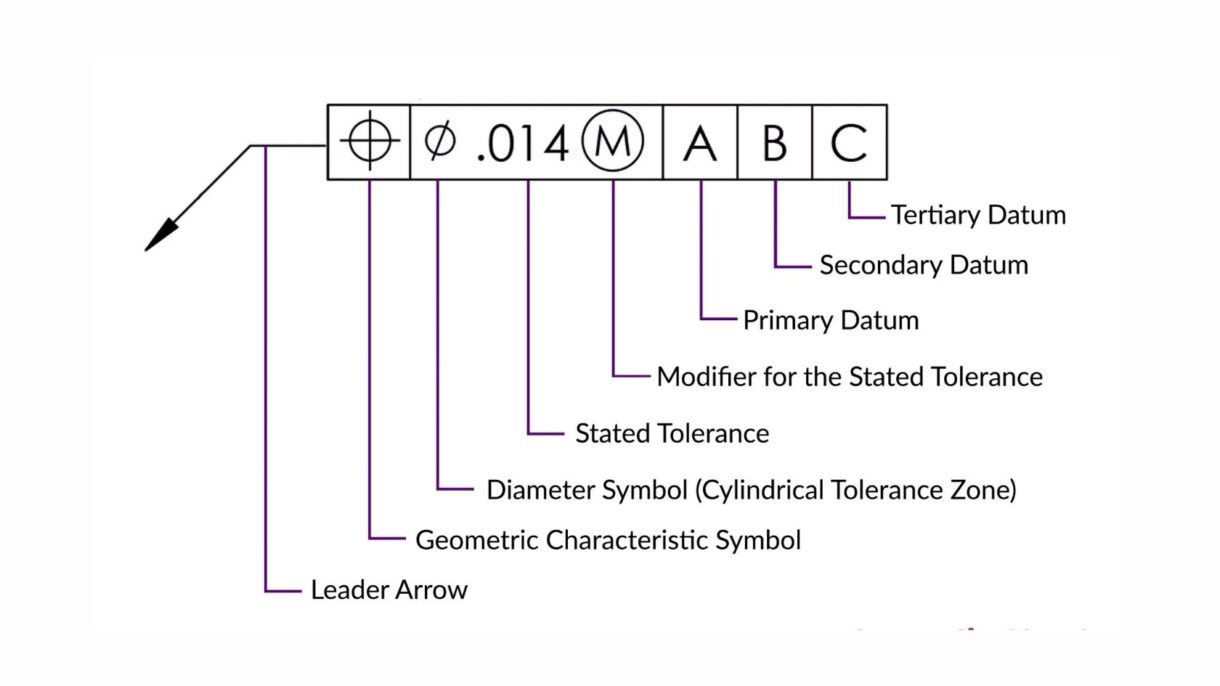
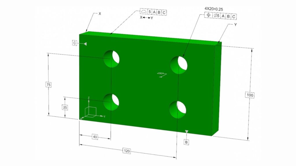
A feature control frame is the foundation of GD and T. It tells you how a feature on a part should be controlled and measured. You read it from left to right, starting with the geometric symbol, followed by the tolerance, and then the datum references.
Each frame defines one requirement. For example, if you need to control the position of a hole, you use the position symbol, then set the tolerance zone, and finally list the datums that the hole relates to. This allows the shop floor and inspection team to measure it the same way.
You must also pay attention to how the frame is attached. Whether it connects to a leader line, an extension line, or is directly under a dimension, that tells you which feature it controls. These details make a major difference in how a part is interpreted and inspected.
GD&T Controls
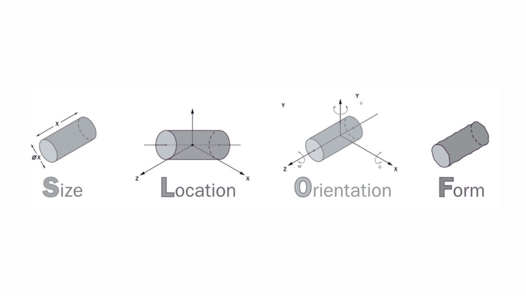
GD and T use a set of geometric controls to define the shape and relationship of part features. Each one plays a specific role. You choose the right control based on how the part functions and how it will be measured. Below are five key controls you will use often in design and inspection.
Flatness In GD&T
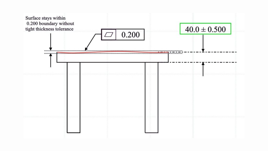
Flatness smacks of a surface being inside two parallel planes. Datums are not involved. You use it where you cannot have waves or peaks on surfaces that are not vital to a location.
This control is typical in the sealing surfaces, sliding surfaces, or mounting surfaces. A surface plate or a height gauge measures flatness by probe points across the surface. It is easy and essential to contact assemblies.
The parts are not rocking, leaking, or wearing out under flatness. It enhances contact without any excess restriction on the location of the part.
Parallelism In GD&T
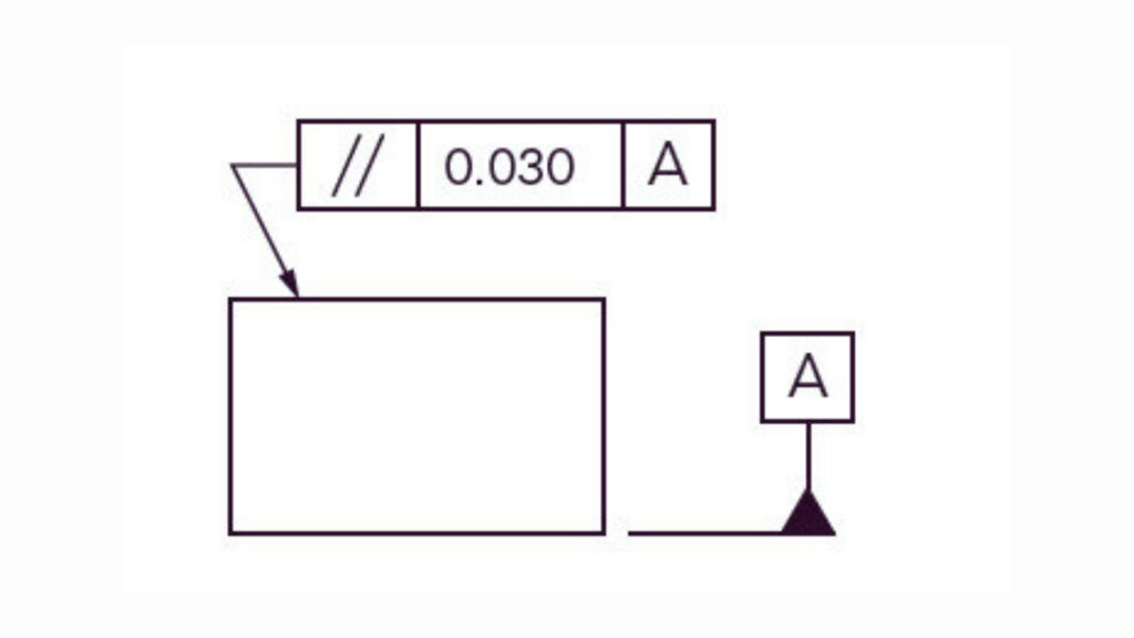
Parallelism is used to regulate the angle between a datum and a surface or axis. It makes sure that the feature remains at a certain distance from a given datum.
You tend to make use of it when two surfaces have to move together or stack appropriately. To illustrate, shafts that are fitted with bearing journals require the same to ensure smooth rotation and non-misalignment.
Flatness or perpendicularity is also used in combination with parallelism. This provides you with a great deal of control, without imposing unnecessary tolerances on non-sensitive regions.
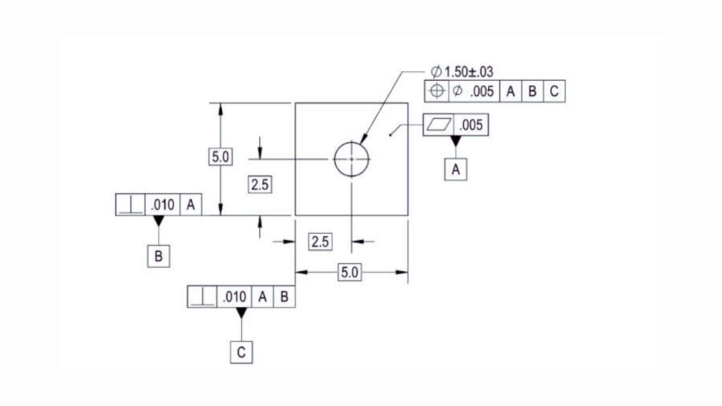
GD&T Position
One of the most important and popular controls is position. It specifies where the holes, slots, or pins should be located concerning the datums. Position provides you with a three-dimensional tolerance zone that is not available in basic linear dimensions.
This is an essential control in assemblies having mating parts. You employ it when you have to have alignment of holes between two or more parts, or when you require precision in fasteners. It will facilitate both specificity and adaptability.
You have gauges or CMMs that measure position. It takes into consideration the size of features, and thus it is more tolerant when features are produced at their limits. This can be referred to as bonus tolerance.
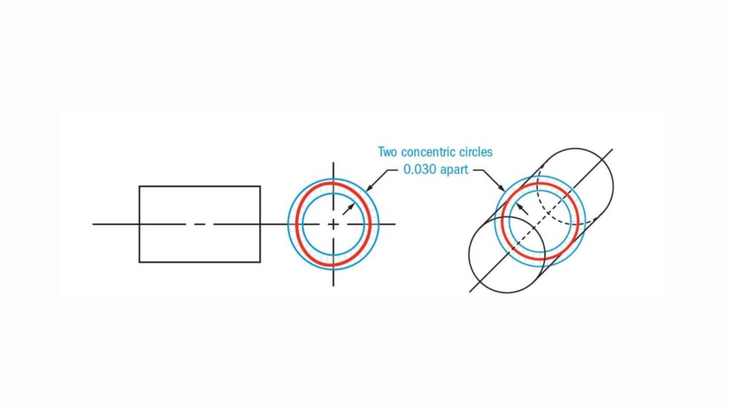
Circularity In GD&T
Circularity or roundness governs the perfection of the roundness of a feature. It applies to cylinders, cones, etc., or any round surface. They do not need any datums since the control is limited to the feature alone.
You make use of circularity in shafts, pins, or bearing seats upon which a deviation might produce vibration or wear. It makes sure a feature does not end up oval or distorted.
It is unlike cylindricity, which also governs straightness and taper. Circularity is easier and perfect only when the round shape is the only thing that matters.
In all directions, the shape of a feature is controlled by the profile of a surface. It draws parallels between the whole surface and the real, theoretical form. Depending on the usage, you can use it with or without datums.
It is the most adaptable GD and T control. You use it when you have tricky curves, tapers, or transitions on a surface that cannot be so easily described using simple dimensions.
It is typical of castings, moulded structures, or aerodynamics. It enables complete control of tolerance on complete shapes, but is still able to be measured using scanning equipment or CMMs.
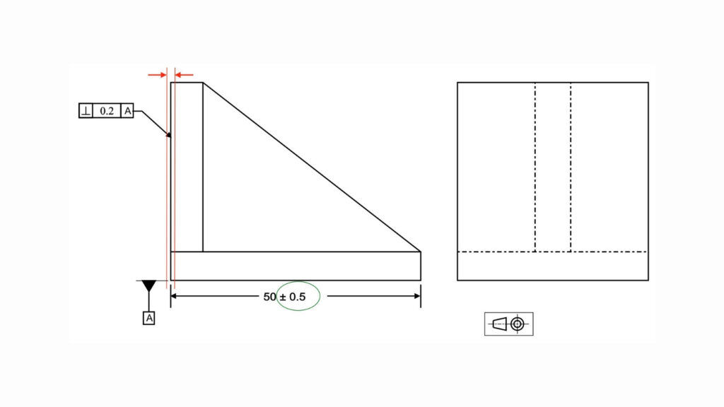
Prependicularity In GD&T
Perpendicularity controls the 90-degree relationship between a feature and a datum. You use it when surfaces, holes, or axes must stay square to another feature during both machining and assembly.
This control is critical for parts that must sit flush or transfer loads evenly. Examples include mounting faces, dowel pin holes, and slots in bracket assemblies. It helps prevent tilt, binding, and misfit in final assemblies.
To measure perpendicularity, you often use a surface plate, angle block, or coordinate measuring machine. It ensures stability and consistency in both part function and part stacking.
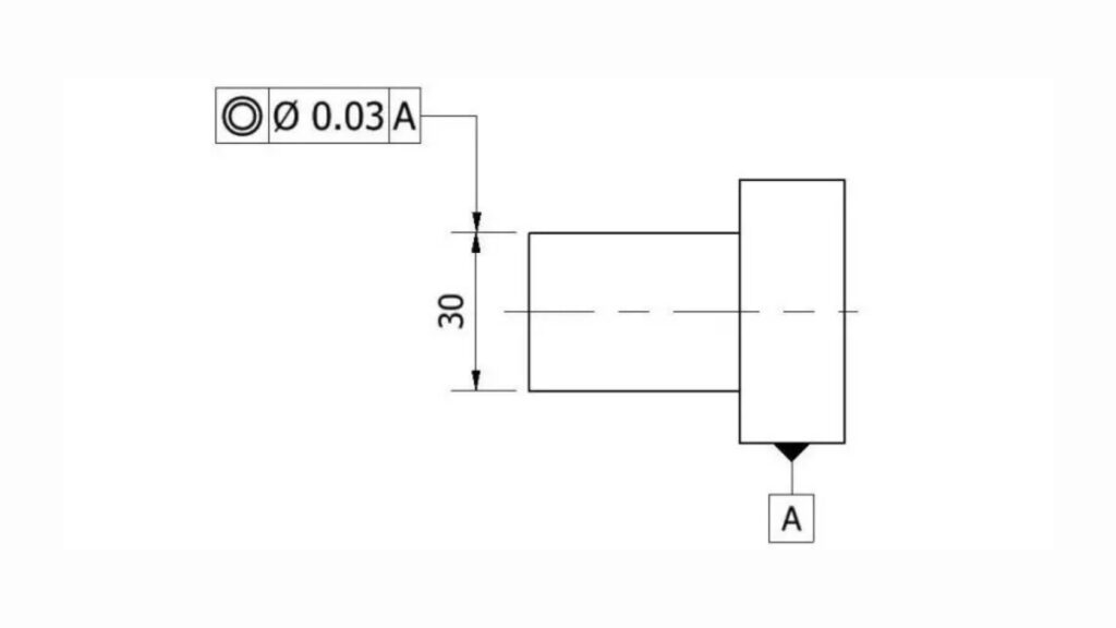
Concentricity (GD&T)
Concentricity controls the central axis alignment between two or more cylindrical features. It ensures that their centres share the same axis within a defined tolerance zone.
This control is useful in rotating parts such as shafts and bearings. If the axes do not align, it can cause imbalance, vibration, or early failure in use. Concentricity solves that by forcing the average centre of all cross-sections to match.
Unlike position or runout, concentricity is harder to measure and inspect. It often requires a CMM or runout testing rig. You should use it only when needed, due to the complexity of validation.
Datum Reference Frame
A datum is a point of origin of measure. In GD&T, you make a tolerance scheme centered around a set of datums. These tend to be planes, axes, or points of the part that define orientation and location. The proper selection of the atum system is very important to part functionality, repeatability, and inspection.
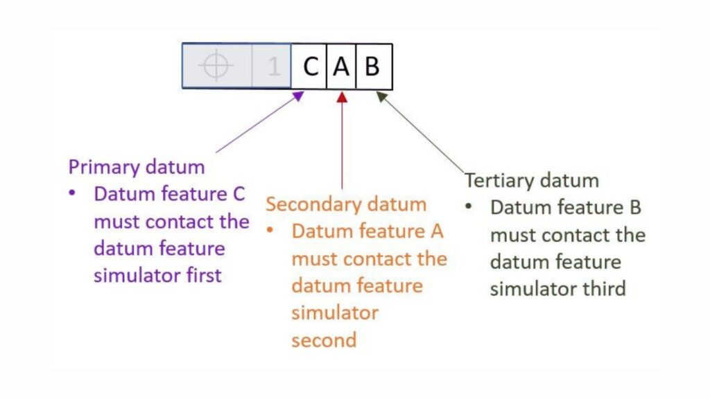
Your first point of control is the primary datum. It establishes the foundation of the positioning of the whole part in the space. Another datum is built up on this feature when a part is resting on this feature.
This surface or aspect has to be the most constant one in touch during assembly. As an example, a flat base, a central bore of a shaft, or a large mounting face are usually good primary datums.
Three degrees of freedom that are locked by the primary datum are movement in the X and Y directions, and rotation in the Z direction. That is what makes it the basis of a uniform measurement and positioning.
Planer Datum
The secondary datum makes the part fit in another direction. As soon as the part lies horizontally on the primary, the secondary holds it in position so it does not swing or rock sideways. It eliminates two additional degrees of freedom.
You will tend to choose a nearby flat face, hole, or slot. This property has to be available and repeatable between parts. The quality of it influences the correctness of the whole measurement chain.
The secondary, along with the primary, aids in locating the part accurately in space, particularly when machining or inspection is to be carried out.
The third level of freedom is eliminated by the tertiary datum. It prevents the motion of the part forward or backward on its last free axis.
This is a little face, edge, or hole that finishes the setup. It should not be in disagreement with the other datums. It principally helps add stability and final alignment.
Although it comes as the final piece of the sequence, the tertiary datum influences the tightness of the control of other features. You have to select it not only conveniently but also based on its functionality.
The physical tool or surface that is used to represent a datum in inspection is a datum feature simulator. It might be a V-block, precision pin, or flat plate.
Simulators must correspond to the theoretical conditions outlined in the drawing. An example i a plane primary datum that requires a smooth surface that is very flat. Any discrepancy or disparity may provide misleading output.
Precision and repeatable setup of parts is made by a good simulator design. When it comes to measurement, it is equally important as the part geometry.
When the entire surface is unusable, datum targets are particular points or lines, or regions that are used. They are normal in castings, forgings, or parts of an irregular shape.
On the drawing, you specify each of the targets. They direct the areas that the simulator touches the part during inspection. This renders the arrangement repeatable, despite whether the component has any surface anomalies or deviations.
Datum targets make it possible that you do not depend on defective surfaces. They provide greater control when applied in the real-world manufacturing, where geometrical perfection is in some cases unattainable.
Inspecting GD and T features requires precise techniques and the right equipment. Each method targets specific controls and ensures parts meet functional requirements. Understanding these methods helps you plan efficient quality checks and avoid costly mistakes.
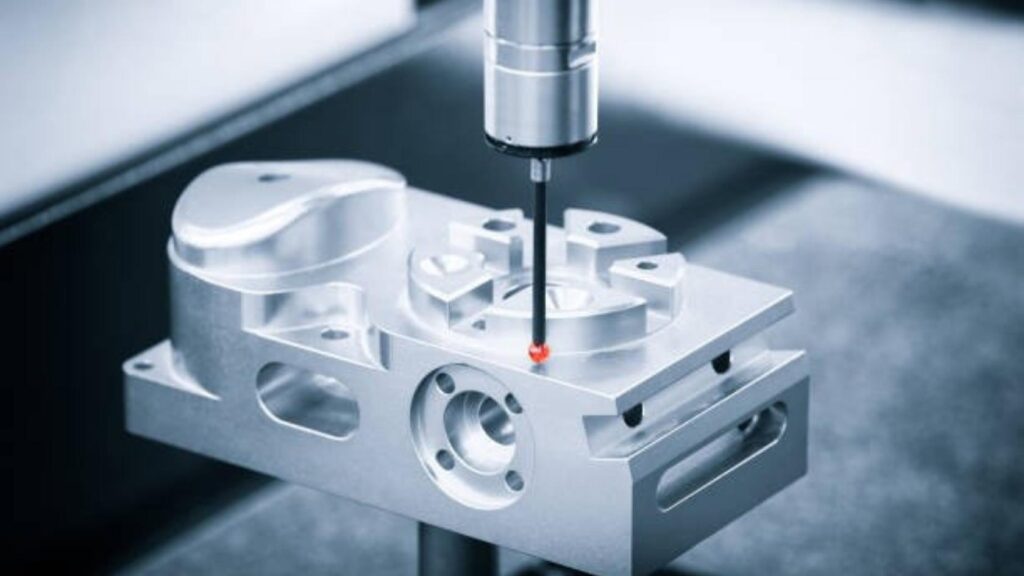
CMM Machine Part Dimensional Checks
The most adaptable GD and T inspection equipment is the Coordinate Measuring Machine. They take a probe to record exact points on the surface of a part. The CMMs are able to measure intricate characteristics such as position, profile, and concentricity with great precision.
You have the CMM programmed to go along with the datum system. It then makes a comparison of the measured points with the theoretical geometry. The process is the best when the batch size is small and the tolerance is high.
The surface plates offer a reference flat plane to determine flatness, parallelism, and perpendicularity of surfaces. Height gauges, in collaboration with surface plates, are used to measure vertical distances and the location of features.
It is an effective combination that is simple. It is also applicable to flat or prismatic components where the measurements follow datum planes. It is cheap and fast compared to CMM, but not very flexible.
The Go/No-Go instruments are specially made devices that are used to confirm that a given feature is within the tolerance range. They are commonly applied to the position, size, or slot opening.
The gauges provide rapid inspection and do not require extensive training of the person carrying out the inspection. They work best in high production volume with high repetition checks required. Nevertheless, they do not identify precise measurement values, but only pass or fail.
Optical comparators use a magnified image of a part, displayed on a screen. This enables profile, straightness, and circularity to be visually inspected.
They are good at working with small details and complex forms. To detect the deviations, you can lay an outline of the part over a template. This technique is rapid and non-contact, but not as accurate as CMM.
Runout tests are used to verify the rotational deviation of a feature, such as a shaft or hole, about a datum axis. These deviations are measured by dial indicators or specialised runout testers.
The inspection of runout is very crucial in the rotating parts to avoid wear and vibration. It is a blend of the circularity and concentricity controls. It is a feasible approach and is common in the world of production.
Applying GD and T correctly improves communication and reduces manufacturing risks. It requires careful planning and understanding of the part's function. Following best practices ensures your drawings are clear and inspection-ready.
Before adding GD and T controls, you must understand how the part works in its assembly. Focus your tolerances on features that affect fit, form, and function. Avoid over-controlling non-critical features, which can increase cost and complexity unnecessarily.
Ask questions like:
This approach helps you apply the right controls in the right places.
Design your datum for the mounting or assembly points of the part. The most stable and functioning feature should be used as your first datum, and then you should add your secondary and tertiary datums logically.
An appropriate data system makes the process of measurement much easier and minimises inaccuracies. It also helps in assuring that the parts are set up by suppliers and the inspectors in a consistent manner. It is better not to use arbitrary or hard-to-measure datums, as they can be a source of confusion and redo.
Your GD and T callouts ought to be understood without a lot of hassles. Take the use of standard symbols and the proper feature control frame. Use all the references of datum and tolerance values.
Do not clutter drawings with such callouts that are not necessary. Only in those cases is it necessary to use notes or additional documents. Effective communication will save time on the floor of shop floor and misunderstandings will be avoided at a high cost.
Geometric Dimensioning and Tolerancing is a vital tool in modern engineering. It provides a clear, standard way to define how parts should be made and measured. Using GD and T helps you control critical features like form, orientation, and position precisely.
Applying the right controls ensures parts fit and function as intended, even when made by different suppliers. The system relies on datums to create a common reference framework, which guides manufacturing and inspection.
Choosing appropriate inspection methods and following best practices in GD and T reduces errors, saves time, and lowers costs. Understanding and applying GD and T correctly is essential for producing reliable, high-quality products consistently.

Rapid Prototyping: All About Process, Techniques, Pros & Challenges & More

All-Inclusive Guide to Laser Cutting Aluminum

CNC Gear Cutting: Process, Techniques & Effective Strategies

Laser Welding: Process, Effective Tips & Techniques for Optimal Welds

Metal Stamping Design: Process, Considerations & Useful Tips

Aluminum Heat Sinks: Process, Techniques & Applications