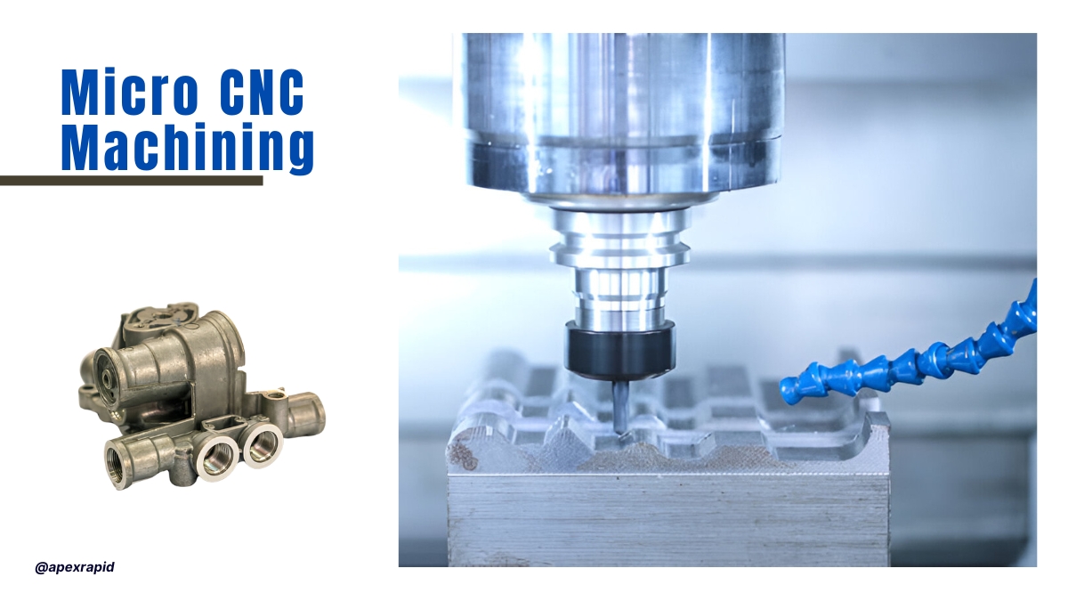
Micro CNC machining solves challenges at miniature part scales. It can work with complex parts under one millimeter in size. Tight tolerances and fine surface control become critical now. This process goes beyond scaled-down CNC methods entirely. You need high-speed spindles and micron-level machine response. Standard fixturing fails when the part size reduces significantly.
At this level, thermal load shifts tool performance sharply. Tiny tools deflect more under even light stress. Tool wear happens fast, often in early tool paths. Every spindle move must hold micron-level positional integrity. You also manage chip removal in extremely confined pockets. That makes toolpath control more than just basic planning.
Micro CNC machining supports sectors that demand zero failure. Think of implants, optical sleeves, or micro-sensor mounts. Any error can break precision or functional fit instantly. Engineers rely on dedicated processes for thermal balance. Your machines, tools, and feeds must all respond intelligently. This approach lets you deliver extreme detail without excess passes.
Micro CNC Machining
Operating on a micro scale changes the way the strategies work. You do not reduce the macro-scale parameters. Rather, it lies in the ability to redefine tool paths, the response of material, and the behavior of machines. The minor instability leads to a large deviation in partial outcomes.
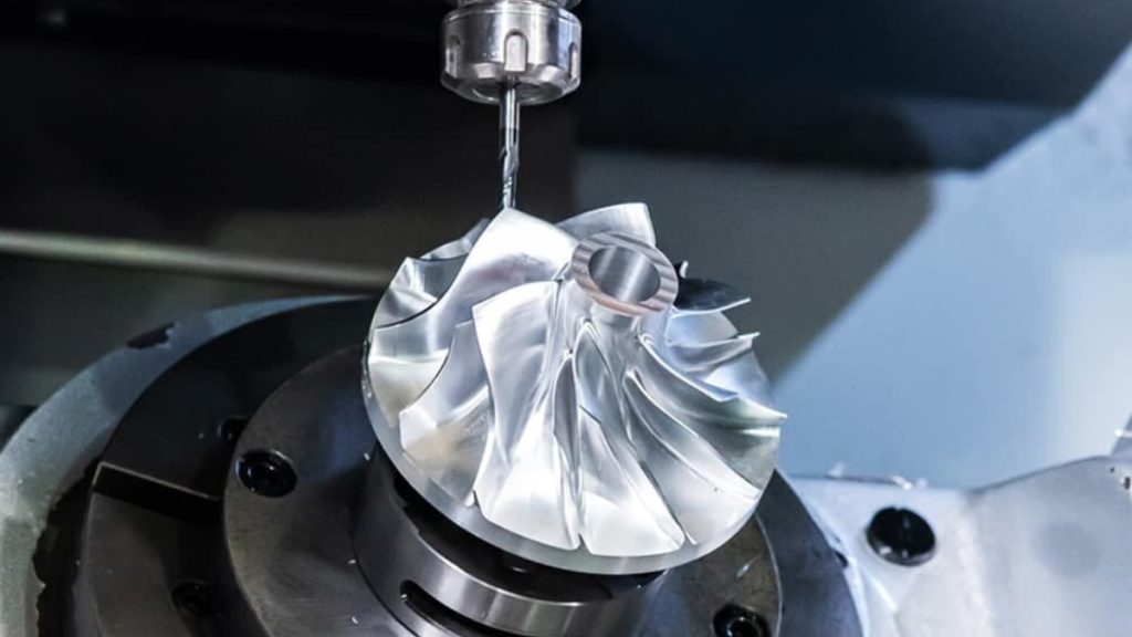
Precision Micro Milling
Micro tools are fine-grained and possess small torque tolerance. Apply tools that have uniform coating on their edges and a sharp radius. Do not use the standard cutters that bend or deform in micro cuts. The ratios of length to diameter have to be equal to the part wall depth.
Small thermal expansion movements move the machine's zero point fast. Employ machines that have a closed-loop thermal feedback loop. The offsets of tools have to be refreshed in real time. Stability in the coolant temperature also counts in long cycles.
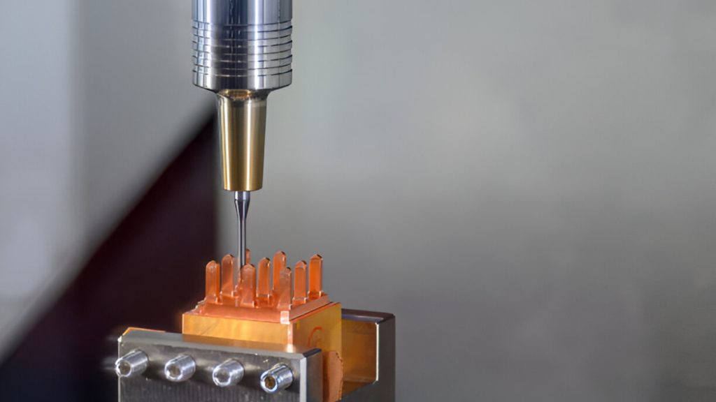
High RPM Spindle
Micro milling needs a spindle of more than 40,000 RPM. Employ super-fine holders that have low tolerance runouts. A tool chatter and damage to the surface are the outcomes of any imbalance. Dynamic balance of micro-scale forces is required for accuracy at high speeds.
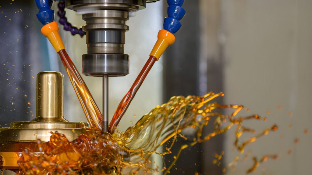
CNC milling machine cutting the shell mold parts with oil oil-cooling method
Micro parts are subject to being damaged or lost by flood coolant. Without flooding the pocket, oil mist comes into contact with the tool. This also averts welding of chips and saves tool life.
Micro parts are too slim to deal with a normal clamping force. Apply vacuum plates, magnetic chucks, or homemade soft jaws. Make geometric correspondence between the match fixture and the part. A mere 0.01mm of a bend can damage a micro feature.
Contact probes can not be used to check micro features. Operate non-contact metrology on the high resolving optical measurements. Check height, thickness of the walls, and the edge finish visually. Dimensional mistakes are also flagged immediately by surface reflection patterns.
The behavior of material at the micro scale is not similar to that of bulk machining. Precision is influenced by such characteristics as grain structure and hardness. The materials you use have to have fine detailing and edge retention. All alloys behave differently when they are subjected to a situation of less tool engagement.

Fine Grained Metal
When grains of the materials are large, micro features break apart. Metals with small particle sizes lower the chipping and tool dragging. They also have uniform strength in micro walls, even in their thinness. This leads to good cutting conditions and an increase in tool life.
Before the material removal takes place, ductile metals can deform. This brings issues of repeat passes in shallow cuts. Work hardening causes more load on subsequent features on the tool. Limit cold flow by the use of keen tools and adaptive speeds.
Tight Tolerance Machining
Chip materials are brittle and break when engaged at low forces. This has an impact on corners and transitions on micro features. Finishing may bring cracks into the working areas.
Even the certified metals can behave in another way on the micro level. Try on real material lots and then produce. Check the burr, finish and the patterns of evacuation of chips. This analysis is useful in maximizing the speeds and feed profiles.
Micro parts whose ribs are long or webs are thin are anisotropic. This consists of materials like drawn aluminum or magnesium. Strength can change in directions, and this can lead to inaccuracy in dimensions. Entry paths of plan tools are to be determined using grain flow orientation.
The presence of contaminants alters the tool-chip interaction to a large extent. The remnants of the films or oil spots lead to burning/smearing. Clean the components by use of ultrasonic cleaning before nd after machining. This saves on fine detail and enhances post-bonding
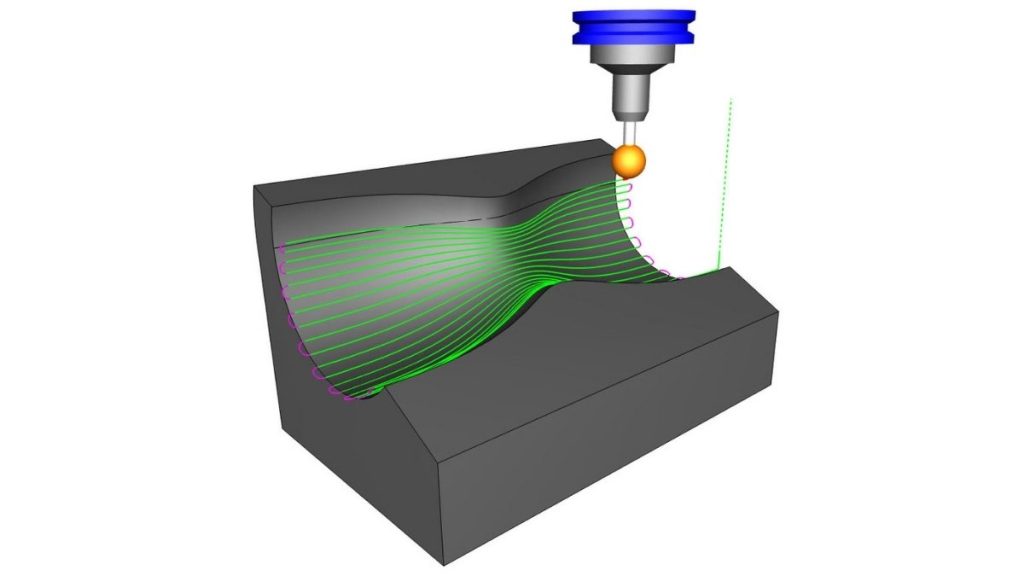
Tool Path For CNC Micro Machining
Deep and narrow features can be problematic for our micro CNC machine. The chances of disruptive interaction between the tool, vibration, and chip removal grow. Effective toolpath strategies are essential in achieving accuracy and reducing tool wear.
The lower radial loads per pass are needed in high aspect features. Minimized lateral force and deflection are due to the reduction of the stepover. It also aids in guarding feature walls against undesirable taper. Make regular shallow cuts in the entire depth.
Straight plunges have a danger of getting chipped in the narrow channels. Toolpaths are trochoidal and keep the tools in a state of constant load. This lowers heat accumulation and enhances chip flow. Application is in slots, keyways, and precision grooves.
Long cuts that have uniform motion can increase runout. Toolpath segmentation gives re-centering points. It also reduces the occurrence of thermal drift and tool chatter.
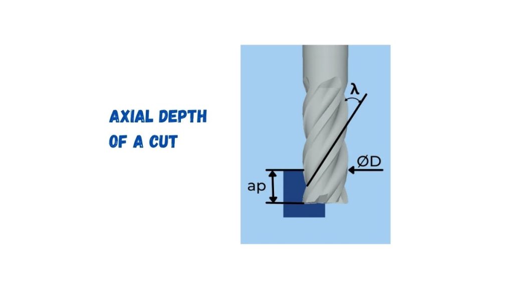
Axial Depth of a Cut
The depth of cut has to correspond with the ratio of the tool diameter. In the case of micro end mills, the depth must not be more than 5 times the diameter. Greater penetration brings in bending and rubbing against the walls. So, take several passes and fewer feed in the deep zones.
Small-diameter tools can be broken in direct vertical entry. The axial load is spread out within motion using entry ramps. They too inhibit formation of burrs at entry port. There must always be a simulation of ramp paths to clear the tool and avoid walls.
The coolant has to move along with the tool movement within passages. Deliver through tool delivery or with high-pressure micro nozzles. The use of synchronized cooling assists in the cleansing of debris and minimization of micro welding.
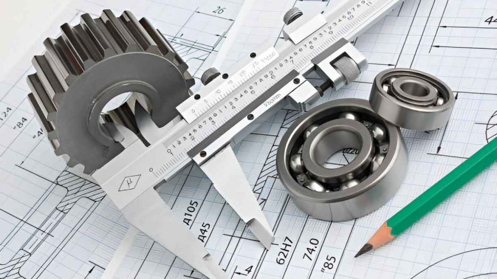
The micro CNC parts inspection of dimensions requires special equipment. The accuracy or range of the conventional calipers or probes is not very precise. The presence of high-resolution measurement tools is necessary for the validation of the accuracy at the micron level.
The digital microscopes and optical comparators are used to view clearly. Their inspection is on the edge definition, radius, and micro contours. These instruments do not cause surface damage to measurements. They are well for one-walled or fragile micro parts.
In ultra-fine surface finish checks, interferometry is favored. It records vertical resolution in nanometers(nm). In general, Engineers apply it to check out texture and flatness. It is appropriate to use it on surfaces and lens finishes.
State-of-the-art vision systems offer automated measurement procedures. Such systems read whole parts and take out profile information. They are verifiable in a short time against CAD, but without any physical contact. Small-batch runs are ensured to be of quality with repeatability of one micron.
Touch-trigger probes are effective on smooth surfaces,l ike hard surfaces that are flat. The CMM machines measure holes and hole locations, bores, a nd slots. Probe force is regulated appropriately when calibrated well. This prevents distortion of the feature during inspection.
Variation is noticed earlier in the statistical process control. Measure the track in several parts of production. Operate it to indicate wear of tools or drift of the machine. SPC in micro-machining brings about repeatability under high tolerances.
In micron-scale CNC machining, the material behavior is not simply scaled down. The interaction between the cutter and the chip is more random at the sub-millimeter scale, which requires process planning and ongoing validation.
The thickness of the chip may be equal to the tool edge radius at small depths. This size effect decreases effective cutting and augments plowing. Rather than shearing, the tool rubs, increases heat, and wears. The tools that you have to select should have very sharp cutting ends.
Ductile metals such as stainless steel or copper become hard with shallow cuts. That leads to chipping of tools as well as uneven surfaces. Apply coolant and reduce areas of contact by varying angles of engagement.
On a small scale, part surface sometimes cuts across individual grains. That causes differences in toughness and tool bending. The micro tools can be deflected down gentler grains, which alters the direction of the path. Apply lower feed speed and cross-cut passes.
Small cutters create an edge built up. The material adhesives alter edge geometry. The results of that are a poor surface finish and uneven geometry of parts. Use high-pressure air or MQL on the control to lower the adhesion.
When your project demands sub-millimeter precision and absolute consistency, ApexRapid brings unique micro-machining expertise to the table. We specialize in machining miniature parts with tight tolerances, fine surface finishes, and intricate geometries. Our advanced multi-axis CNC platforms and in-process quality controls ensure every component meets exact performance and dimensional standards. Whether you're working in optics, microfluidics, or precision instrumentation, we understand the margin for error is near zero, and we’re equipped to deliver.
Our company supports rapid prototyping and short production cycles with the same rigor applied to high-volume runs. Our team collaborates directly with your engineers to understand functional needs and material constraints at the micro level. From tool selection and fixture design to thermal compensation and burr control, every detail is optimized for miniature scale production. This level of refinement helps reduce failure risk and gets your parts right the first time.
Micro CNC machining offers micron-precision in miniature geometry parts. You work with tight tolerances and exact surface finishes. These parts often go in medical, optics, or aerospace devices. You cannot afford errors in shape, size, or alignment.
At ApexRapid, we machine micro parts with full control. Our team handles size, load, and material response. You receive clean parts with stable edges and clear geometry. We optimize the process to match each design demand. Whether it's prototyping or production, we meet your specs.
Q1: How precise is micro CNC machining at ApexRapid?
We hold tolerances down to 5 microns or tighter. You get accurate and clean components every single time.
Q2: What materials do you support for micro components?
We can precisely machine aluminum, titanium, steel, and high-end plastics. Our setup changes based on your material’s behavior.
Q3: How do you avoid burrs on micro features?
We use sharp tools, slow feeds, and soft finishes. Parts are inspected and deburred before final delivery.
Q4: Can I order low-volume micro CNC parts here?
Yes, our services support both prototypes and small batches. We deliver fast without compromising part quality.

Laser Welding: Process, Effective Tips & Techniques for Optimal Welds

Metal Stamping Design: Process, Considerations & Useful Tips

Aluminum Heat Sinks: Process, Techniques & Applications

Aluminum Car Parts: Benefits, Techniques, and How to Source

CNC Medical Machining: Process, Techniques & Applications

Complete Automotive Machining Guide: From Discontinued Parts to Custom Solutions