CNC chamfering is the process of cutting angled edges on a part. It removes sharp corners and adds a clean, finished look. Chamfers also improve safety, fit, and ease of assembly.
This process is common in both metal and plastic parts. It helps parts seat properly, prevents edge damage, and supports coating or finishing. Chamfering can also reduce stress points in high-load components.
In CNC machining, chamfers are easy to apply using specific tools and programmed toolpaths. You control the angle, width, and location with precision. Knowing how and when to chamfer improves both part quality and shop efficiency.
CNC chamfering uses angled tools and programmed movements to cut beveled edges. The toolpath follows part geometry while maintaining a set chamfer depth and angle. Chamfering can be done on outer edges, holes, or complex contours.
You can create chamfers in two main ways. These include:
Both methods depend on tight control of spindle speed, feed rate, and tool positioning. In most cases, the tool cuts along a predefined edge with a slight offset, trimming material at a fixed angle.
CAM software allows you to define chamfer width, depth, and approach strategy. You can apply chamfers during contouring, drilling, or finishing cycles. The result is a consistent edge break that improves appearance, safety, and part performance.
Tools used in chamfering are of different shapes, uses, and applications. Your choice of the right tool is based on your part geometry, material, and edge quality requirements. The right tool makes the difference by resulting in finished cuts and the reduction of time.
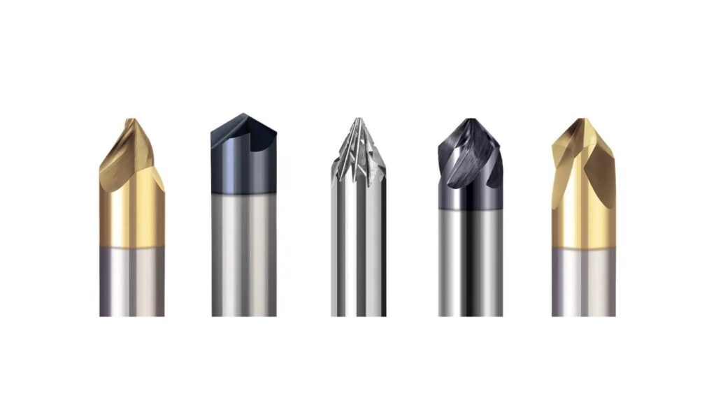
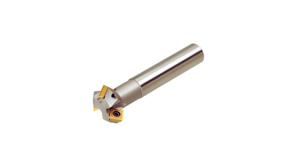
Common Types of Chamfer Mills
The CNC chamfering tools are mostly chamfer mills. They have cutting faces that are typically angled 30, 45, or 60 degrees. The shearing edges cut the material on sharp edges.
Chamfer mills provide clean, consistent cuts on the part outline, or around big holes. They are optimal in case of simple shapes, predictable tool-paths, and the highest repeatability.
Spot Drills Milling Cutters
Spot drills are short, stiff tools that are regularly used to start holes. And they are also good at chamfering small holes. They can be used with no tool deflection since these are rigid in design.
They are the best when you have to mix the jobs in one paint- [Spot-] drilling and chamfering. Their range is small, though, and they are not suitable when dealing with exterior edges.
Deburring Tool
Deburring tools cut sharp edges and burrs, and protruding materials in the process of roughing. These may have spring-loaded or floating heads to track uneven shapes.
They are helpful when it is needed to complete the cycles, especially on soft metals or plastics. Deburring tools use light chamfers and are not ideal for making deep and exact cuts on the edges.
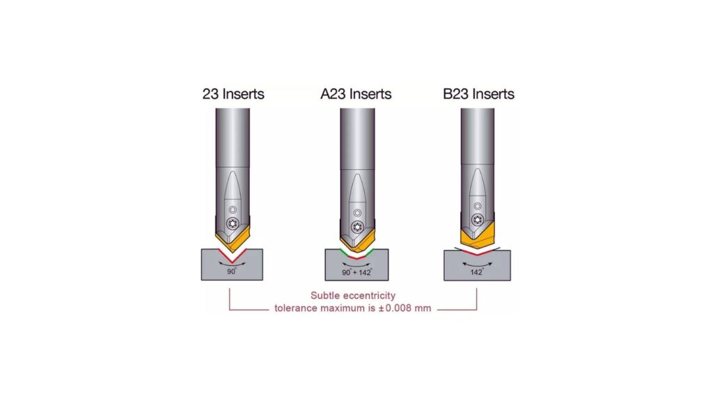
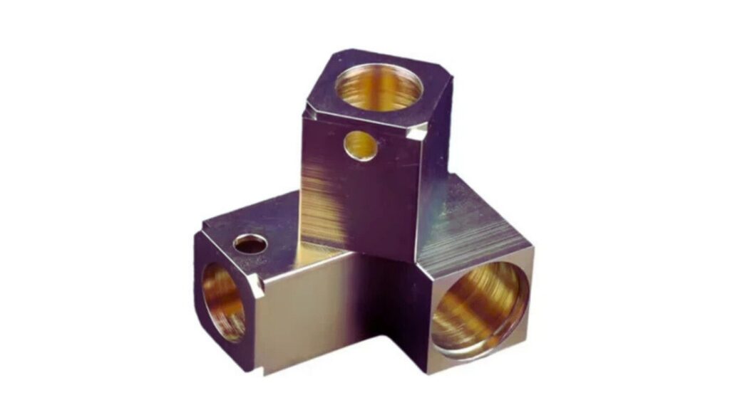
Indexable Chamfer Tool
These are replaceable insert tools that are at fixed angles. They are used in jobs that have large volumes or cutting hard materials. Indexable tools minimize time wastage because the insert may be replaced within a short period.
Apply them where you are required to have a long tool life, repeatability, and durability in your job. They can be used on steel, stainless, and titanium alloys in the automated CNC manufacturing.
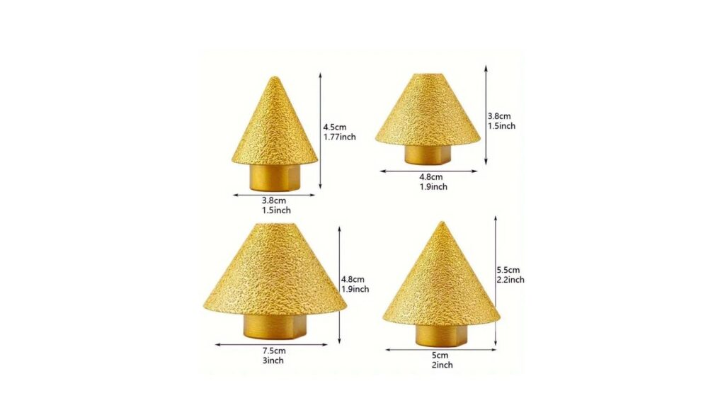
Drill Bit Conical Engraving
Light chamfering can be performed with engraving tools, particularly on small components or on fine geometries. The tools are very sharp-edged and can be used to break edges.
They are useful for fine work, electronics, or decorative edges. Take care to use them-they are not heavy material removal tools.
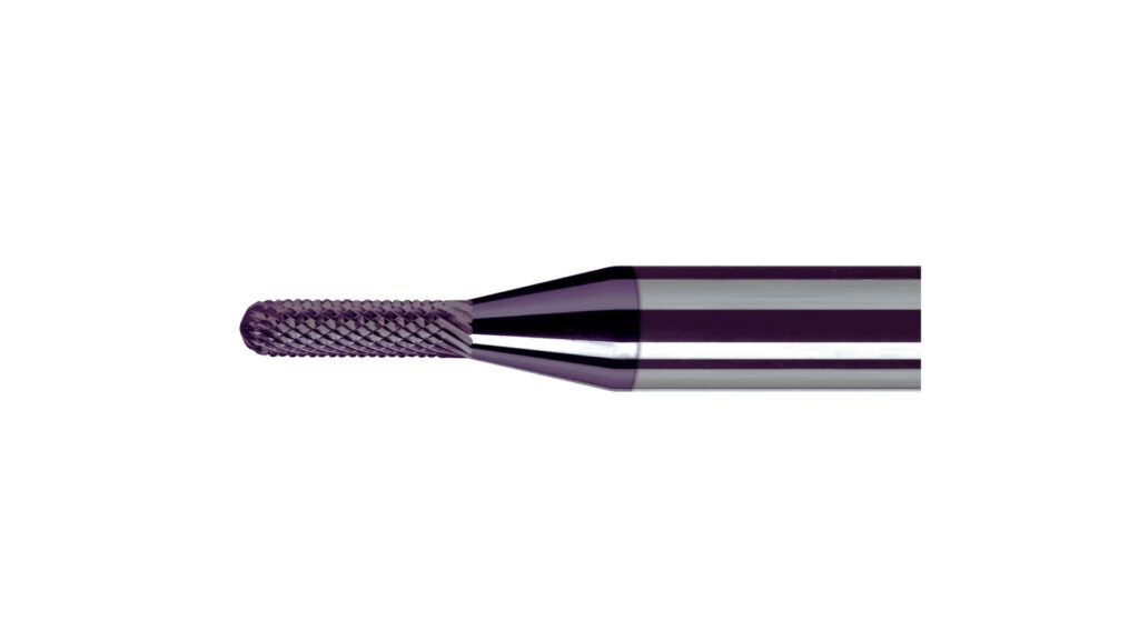
alt: Bore & Back Chamfer Tool
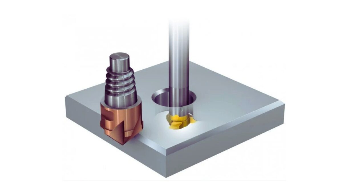
Back chamfers Back chamfering tools cut behind an aspect, such as the bottom of a hole or slot. These are tools that are inserted through a bore and then expand or swing out to chamfer the hidden edge.
They are perfect in internal features that a regular tool can not access. They are more difficult to code, yet they are vital in aerospace and hydraulic components.
Multi Axis Chamfering
The tools adapt to changing angles in multi-axis machining. They are applied when the geometry of the part varies or when it needs angled edge breaks on surfaces.
Apply such heads on 5-axis CNC systems. They permit interactive use of chamfer angle, depth, and location. They work on geometry pieces with multifaceted outlines.
CNC chamfering enhances the quality of the parts, eliminates sharp edges of the parts, and facilitates the assembly of reliable parts. However, it takes a lot more than that to achieve consistent results, though. It has to be well planned, well programmed, and well set up for the machine. These are the best practices that will guide you to overlook the common mistakes and make all the chamfered edges under control.
Good chamfering is based on the choice of tools. Most edge breaks and outer profiles are made using a fixed-angle chamfer mill, usually at 45 degrees. Spot drill or center drill is more suitable for holes. Tools with back chamfering are most suited for internal surfaces or blinded characteristics.
Adjust the angle of the tool with your design intent. When you have a chamfer callout that has an exact angle and depth, you need a tool that makes the exact angle of the callout. The incorrect tool geometry may mess up the chamfer or destroy the edge.
Chamfer depth is not gauged as a flat cut (i.e., in the same way). The tool cuts under an angle, and therefore, you will have to calculate the correct vertical and horizontal engagement to fit your desired chamfer width. A tiny bug in programming at this point usually causes an underdeveloped or an overdeveloped feature.
With the CAM software of your choice, you may plan out the precise shape of the chamfer. Enter the depth of the chamfer you want, and the software will calculate the desired depth. It is always a must to check these values in advance before executing the first part.
Chamfering is not a high-speed operation; chamfering is a light finish pass. When machining, always employ slower feed rates than when you are doing roughing. This is to achieve a clean, accurate edge on the tool without chatter or burr occurring.
It is better not to plunge the tool straight into the material. Rather, a lead-in or ramping move can be used to get the tool involved progressively. This enhances topography and increases tool life. External profiles, chip evacuation, and edge quality can be improved by considering climb milling.
Overcutting occurs when the chamfer tool is kept in a corner too long, causing the cut to be deeper or unbalanced. This occurs normally in situations when the path of tools is not optimized for sharp turns or small radius.
Move your toolpath so that there is a continuous tool engagement. Where this is a problem, corner slowdown settings or other linking moves can be used to cut down dwell time at sharp corners. It is always wise to simulate the path and to study the corner behavior prior to running the part.
Chamfer tools are worn as opposed to end mills. Depending on the intensity of edge wear, there is the possibility of the chamfer width wearing down as time goes by, even though your program may have been the same. Tool wear compensation in your CNC control allows you to make small corrections without having to rewrite the code.
Keep checking the edges of tools with magnification. When a visible wear comes up, you can slightly adjust your wear offset to give you the right width back. When tool wear surpasses tool tolerance, it is apparent that you have to replace that tool at once to preserve the quality of the part.
When it comes to tolerance, it is not enough to do visual checks. Apply accurate tools of inspection, e.g., optical comparators or edge measuring calipers. During hole chamfers, depth gauges with the measure of width and angle should be used.
Measure the initial of each of the setups. In case of necessity, correct tool offsets or machine zero points. Install inspection stations in your production process where you gauge whether chamfers have been implemented every time you make a production run.
Any good outcome has to be replicable. Once you dial in a chamfering, it is a good idea to take note of the type of tool, angle, feed rate, spindle speed, depth of cut, and offset. This avoids wasting time on setup in future assignments and enables other machinists to be able to duplicate your process.
You may enter this information into your CAM templates, setup sheets, or machine control notes. Well documented, one will not perform guess work, and the second run will be identical to the first run.
Small chamfering errors will lead to rework, tool wear, or poor quality of parts. The majority of the errors are based on the setup problems, improper application of the tools, or improper programming. The following are the major issues encountered by machinists in the process of chamfering and how they can easily be avoided.
Inappropriate Chamfer Design
This is one of the commonest errors. It normally occurs because the programmed depth is not equal to the tool angle, or a worn tool decreases the actual cut.
To prevent it, depth should always be calculated at the angle of the chamfer. Determine the size of the chamfer by simulating the chamfer size using CAM software and then cutting. Measure the width using calipers after the first pass, and correct offsets, where necessary.
In case the tool is not properly set, the chamfer may move or cut out of balance. The deflection of tools also occurs on small-diameter tools or long overhangs.
Ensure that the tool is fixed in a hard holder and well seated in the spindle. Where feasible, make the length of the tool short. Deflection is also decreased by lower feed rates and light cuts.
Exit Burr Formation in Chamfer Milling
On soft materials, burrs can easily occur at the end of a chamfer pass. These may come between the part fit and finishing.
Sharpen up tools and feed reduction at the exit point. Put a little lead out in the toolpath to clear the edge. In soft alloys, consider changing to climb milling to minimize the size of the burr.
A poor type of tool may lead to chatter, a lack of surface finish, or feature omission. As an example, a small hole will not be cut using a flat chamfer mill.
Correspond the form of the tool and its angle to the geometry. Spot drill holes, indexable chamfer tools in hard materials, and back chamfer tools in internal edges.
Toolpaths should not overlap or repeat; otherwise, they may make deeper chamfers or rough edges. This is normally caused by bad CAM settings or wrong lead-in and lead-out movements.
Simulate every path so that it has no overlaps. Establish tool entry and exit so that one does not cut the same edge twice.
To design a part with chamfers, one should do more than enter angled edges. To achieve the best results, engineers are advised to design chamfers depending on manufacturing constraints, accessibility of tools, as well as tolerance requirements. Such instructions assist you in producing easy machining parts of the same quality.
Apply common chamfer angles such as thirty, forty five or sixty degrees. These fit the majority of tool shapes and make it easier to set up. Do not use strange angles unless it is necessary for the functionality.
With regards to width, use values that permit the common tool sizes to achieve full depth. Minute alterations in angle or width may affect the choice of tool and machine setting.
Chamfers in deep holes, small slots, or deep pockets may be difficult to access. There is a possibility that standard tools would not fit, and long-reach tools could bend.
Internal chamfers should be designed only when there are reasons to do so. Where necessary, provide more access space or other edge breaks such as radii. Take a look at blind holes back chamfering tools.
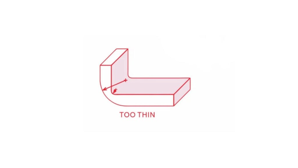
Chamfer tools need room to enter and leave without going too far. Poor surface finish or collision of tools may occur when there is no clearance on small pieces or at an intersection.
Make sure that you have a lead-in and lead-out room in your geometry. Where you can, make surfaces just a little beyond the chamfer so that the tool has room to get its full travel.
Should the size or angle of chamfering influence part performance, then a tolerance range should be specified. Such generic notes as break all sharp edges may result in unreliable results between batches.
Label the width and the angle on the drawing. In case a visual break suffices, it is necessary to note that the chamfer is decorative and does not need inspection.
Composites that have dozens of chamfered edges slow down the cycle time and tools. In case your part has repeated chamfered features, check your toolpath strategy and tooling arrangement to minimise machining time.
An indexable chamfer tool should be used in production to minimize tool change-overs. To achieve repeatability in running, test, and record your chamfering process in high-volume runs.
CNC chamfering is more than a cosmetic step. It improves edge safety, helps parts fit together, and increases overall part quality. With the right tool, accurate programming, and good process control, you can create clean, consistent chamfers that meet tight tolerances.
Start with proper tool selection based on your part geometry and material. Program chamfer depths using correct angle-based calculations. Keep feed rates low and toolpaths optimized to prevent wear and rough edges. Always inspect the first piece and monitor tool condition during production.
By applying best practices and avoiding common mistakes, you reduce the risk of tool failure, rework, and dimensional errors. Well-designed chamfers are easy to machine, easier to inspect, and give your parts a clean, professional finish every time.
What is the standard angle used for chamfering?
Most CNC chamfers use a forty-five-degree angle. This matches common tool geometries and simplifies setup. Other standard angles include thirty and sixty degrees, depending on design needs.
How do I calculate chamfer depth for programming?
Chamfer depth depends on the angle of the tool. Use CAM software to enter the desired chamfer width, and let it calculate the correct vertical depth. Manual calculations use trigonometry based on the angle and width.
Can I chamfer inside holes or pockets?
Yes, but only with the right tool. Use back chamfer tools for internal features or blind holes. Standard chamfer mills usually cannot reach deep or obstructed areas without collision risk.
What causes inconsistent chamfer sizes?
Inconsistent sizes usually come from worn tools, incorrect offsets, or improper tool angles. Always inspect the first part, check tool condition, and make sure your machine's zero points are accurate.
Are chamfers better than radii for edge breaking?
It depends on the function. Chamfers are easier to machine and inspect. Radii are better for reducing stress concentrations in high-load parts. Choose based on performance, appearance, and machining access.

Aluminum Heat Sinks: Process, Techniques & Applications

Aluminum Car Parts: Benefits, Techniques, and How to Source

CNC Medical Machining: Process, Techniques & Applications

Complete Automotive Machining Guide: From Discontinued Parts to Custom Solutions

Custom Automotive Parts: Methods, Challenges & Choosing the Right Manufacturer

What Is a Vacuum Casting Service? Techniques, Process, & Applications