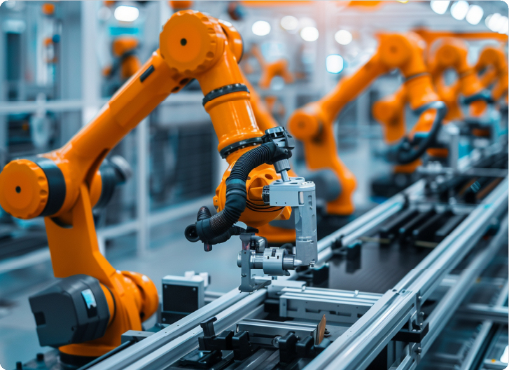
Precision sheet metal fabrication isn’t just cutting flat parts. It helps you turn raw sheets into real-use components. Whether it’s for robotics frames or medical housings, precision always remains a critical concern..
You don’t just want a good part; in fact, you want exact parts that perform as desired. Because a slight 0.2 mm bend shift can quickly ruin the part alignment. That’s why you use precision CNC lasers and brake presses with tight control. However, advanced setups can even track material springback and tool wear in time.
Each part you produce must fit into a system. If one hole is off, the build stops. Precision also affects airflow, fit, and surface finish. With high accuracy, you get repeatable results across every production batch. This article explains precision fabrication, its main techniques, and considerations for optimum results. So, keep on reading.
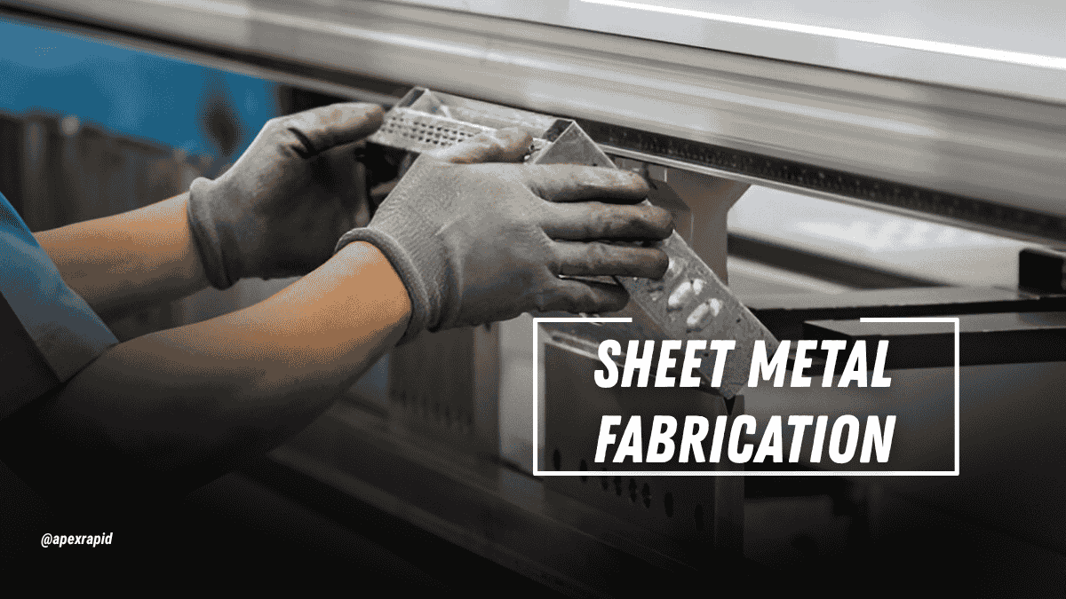
Custom Sheet Metal Fabrication
Precision sheet metal fabrication is a controlled fabrication technique. It involves cutting, forming, and assembling metal sheets to the required specification. Each method follows strict dimensional and tolerance control.
The process begins with technical drawings. You need to create a digital footprint of part models in terms of a CAD model. This guide the equipment to effectively shape as per design. At every stage, accuracy is verified against defined tolerances.
Unlike conventional fabrication, this method gives repeatable precision. It relies on CNC machinery, quality jigs, and in-process inspection. Besides, consistency, fit, and function are critical at the production scale.
Precision sheet metal fabrication has a defined operational sequence. Each step, from design to finishing, demands strict control and planning. Therefore, you need to rely on calibrated tools, trained personnel, and validated methods to facilitate high accuracy. The following sections explain each process in detail, focusing on technical reliability and repeatability.
The first step of precision fabrication is to specify your design requirements. You make 2D drawings or 3D CAD. All dimensional, tolerance, and material requirements are expressed in these files.
Moreover, you develop flat-pattern designs of manufacturing processes. Bend allowances and relief cuts are determined using this step. Precision in this case minimizes the hazard of downstream fabrication.
Once the design has been approved, you get into flat-sheet processing. CNC laser cutting guarantees close profiles and edge quality. You can choose the laser power depending on the thickness and alloy.
Internal features or slots may be done by turret punching. Controlled feed rates prevent thermal distortion. Forming takes place after the cut parts are deburred and re-checked on quality.
You can make components with press brakes that are calibrated to CNC. Every bend is characterized by angle, radius, and location. Positional repeatability is assisted by back gauges and sensors.
The directions of material grain and springback are taken into consideration. Tooling has to be optimal with the sheet thickness and profile. This eliminates cracking, tearing, or angular variation.
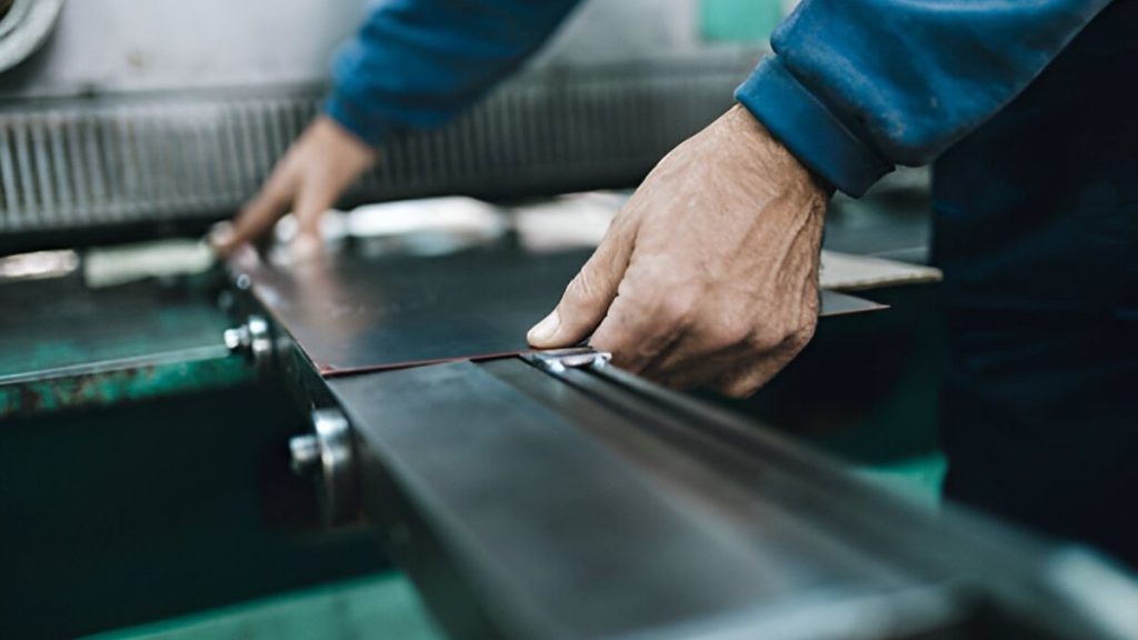
Sheet Metal Joining
Formed parts can then need welding or reinforcement. Depending on the type of materials, you can use TIG or MIG welding. Besides, spot welding and insertion of rivets are usual at this stage.
After forming, fasteners or PEM hardware can be added. Assembly jigs also serve to hold the critical dimensions. This selection is given by alignment and load-bearing considerations.
You use surface finishes depending on the part's intended function. These can be in powder coating, anodising, or even mechanical polishing. These treatments increase resistance to corrosion and make them look good.
All surface processes should not interfere with dimensional tolerance. During coating, it is essential to have masking and racking arrangements. Finishing inspection is to make sure of even coverage and surface integrity.
There are multiple sheet metal fabrication techniques for custom parts. You can select the method based on geometry, volume, and material. Below are some common techniques used across precision manufacturing environments.
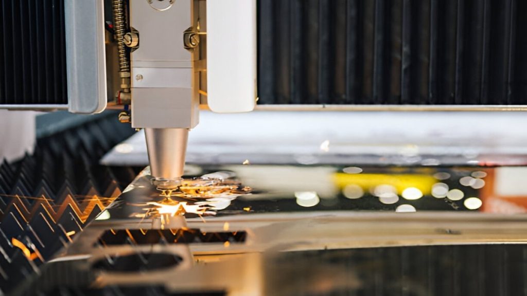
Sheet Metal Laser Cutting
A profiled laser cutting is done using a focused beam. It uses very tight tolerances and minor burring. You may process stainless steel sheets, aluminium sheets, and mild steel sheets.
The approach promotes efficient, high-speed automation and nesting. You can optimize cut speed, focus, and type of gas, particular to each alloy. The quality of edges is determined by the beam alignment and lens conditions.
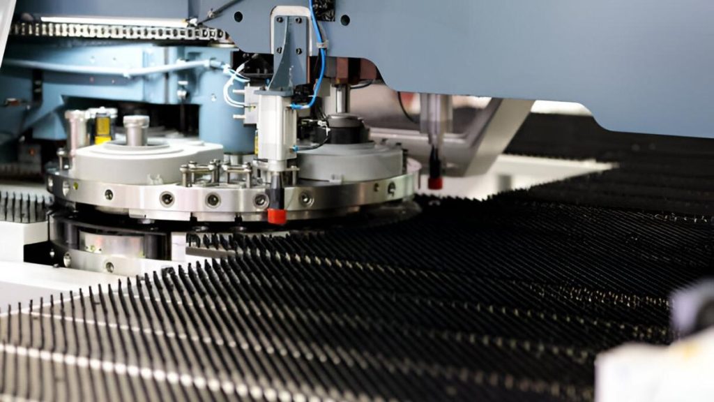
CNC Turret Punching
Turret punching applies the indexed tools in the creation of holes or forms. You use this on louvres, slots, and bridge tabs. It works well at moderate volumes and is recurring. So it is ideal for repeated runs.
The turret head has each tool station preloaded. Cutting, embossing, and marking can be done in a single setup. Accuracy is based on stroke control, depth, and alignment of the punch-die.
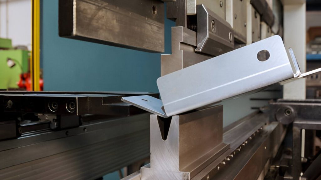
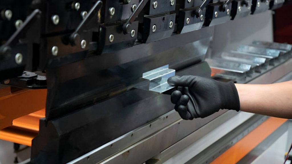
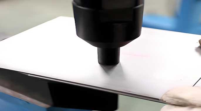
Precision Sheet Metal Bending
It involves bending sheet metal through programmable press brake machines. You precisely control bend angle, force, as well as tooling position. The material behaviour changes depending on the thickness and the direction of the grains.
Sensor technology rectifies the error in springback with instantaneous feedback. Bending the bottom and air bending, both, as well as coining, are possible. To prevent stress or a crack on the surface, you need to change the tooling clearance.
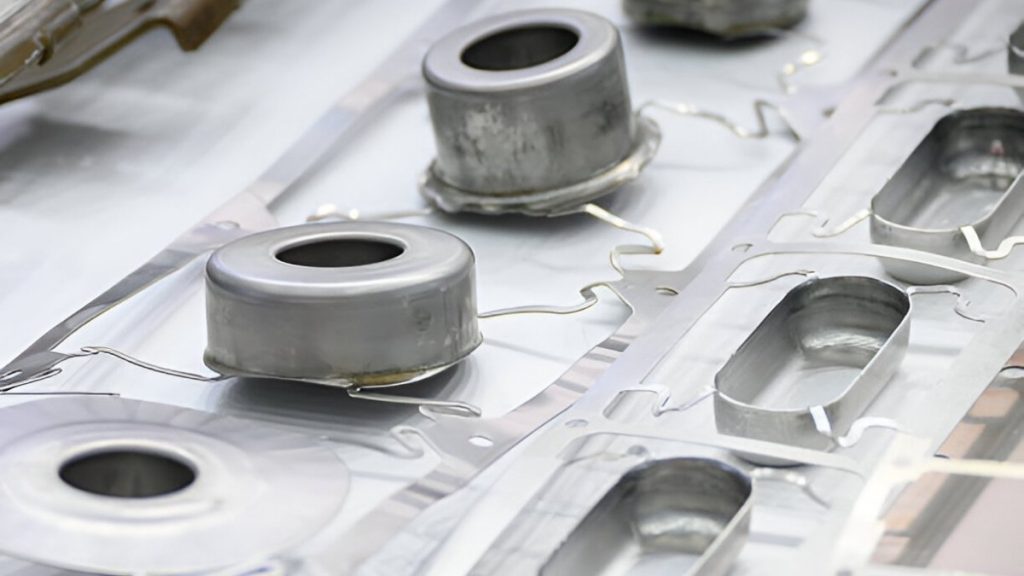
Aluminum Deep Drawing
Deep drawing changes planar sheets into a cylindrical, cupped, or boxed form. It applies to parts that require depth and need no seams. This process can be applied to automotive and electronics enclosures.
When material ductility and tool geometry are considered, success relies on it. You regulate the blank holder force so that it does not wrinkle. Tearing and surface friction are minimized by lubrication and the draw radius.
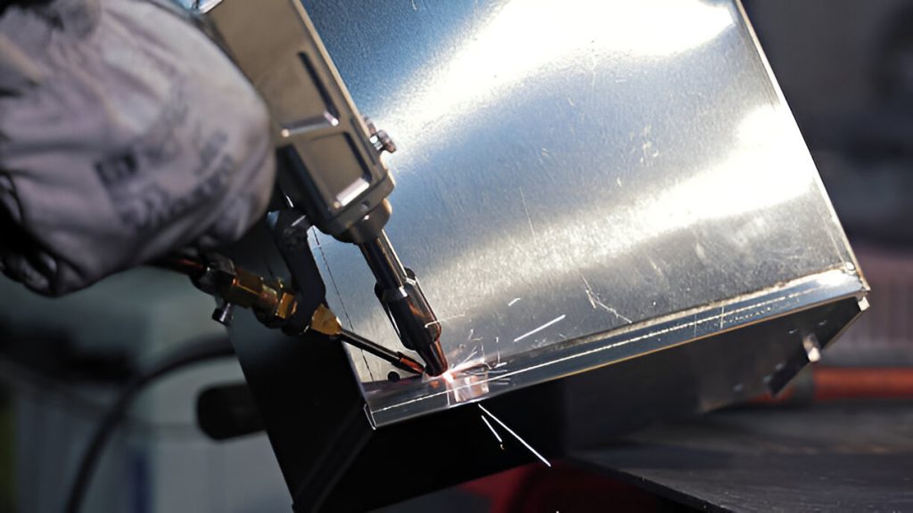
Spot Welding
Welding contributes to sheet metal, which is fixed to form assemblies. You can choose TIG, MIG, or resistance spot welding. Process choice is affected by joint design and sheet thickness.
Fixturing alignment is done during and before welding. The flow of heat is controlled to avoid twisting or bending. Structural reliability is guaranteed by post-weld cleaning and inspection.
You put fasteners on once the bending or forming is completed. This consists of threaded standoffs, nuts, and self-clinching. The components give mechanical threads that do not require tapping the sheet.
The right press force is a requirement of a regular flush fit. The result of misalignment is sheet cracking or pullout under loads. Tooling dies have to be the same diameter as the hardware and sheet gauge.
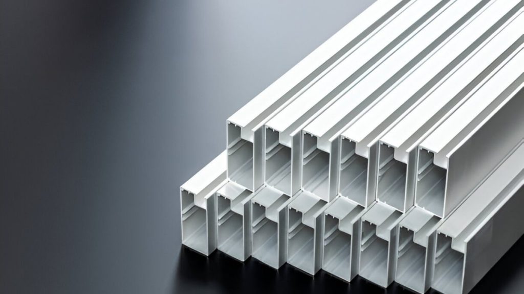
Anodized Aluminum Profiles
Finishing is done to increase the functionality, looks, and corrosion resistance. You can apply a powder coating, anodising, brushing, or zinc plating. The finishing choice is made, depending on the exposure and the part's aesthetic needs.
Masking of threads and mating surfaces is needed in coating lines. You control the temperature, humidity, and dwell times to maintain consistency. After inspection, adhesion and colour consistency are verified in the final inspection.
| Process | Typical Tolerance | Material Compatibility | Typical Applications | Limitations |
| Laser Cutting | ±0.05 mm (up to 3 mm thick) | Mild steel, stainless, aluminium | Complex profiles, tight internal features | Heat-affected zones in thicker sections |
| Turret Punching | ±0.10–0.15 mm | Cold-rolled steel, aluminium | Perforated panels, repeat hole patterns | Tooling limits shape complexity and feature detail |
| CNC Bending | ±0.25° angle, ±0.15 mm linear | All ductile metals | Brackets, flanges, precision-formed enclosures | Material springback affects bend angle consistency |
| Deep Drawing | ±0.10 mm depth, ±0.20 mm profile | Aluminium, low-carbon steel | Cylindrical or contoured housings | Limited to ductile metals with uniform grain |
| TIG/MIG Welding | ±0.30 mm joint location | Stainless steel, aluminium alloys | Frame assemblies, internal seams | Localised distortion, post-weld finishing required |
| Hardware Insertion | ±0.08 mm hole-centre accuracy | Formed sheet metal | PEM studs, threaded standoffs, captive nuts | Requires exact press force and alignment |
| Surface Finishing | ±5–10 μm coating thickness | Steel, aluminium, pre-treated parts | Powder-coated panels, anodised aluminium parts | Dimensional shift; masking required for mating areas |
Precision sheet metal fabrication offers measurable value to engineers. You gain tight control, functional results, and lean production flow. Below are five focused benefits essential to technical teams.
You attain tolerances of up to 0.05 mm. This removes post-machining or shimming needs. Bends formed and cut edges correspond to the drawings directly.
Every component fits without handwork or modification. You keep functional geometry between batch one and batch ten thousand.
Your sheet layout planning is done on high-efficiency nesting. Laser kerfs have a small thickness and minimize the amount of edge lost. Structural material is removed, but nothing extreme.
Scrap is anticipated, and it tends to be less than 10 percent a sheet. It is economical on stainless steel, aluminium, and coated steel.
You make parts out of CAD drawings without any tooling delay. Laser profiles and bends are model-related. It does not require any dies or mould at any given point.
This will allow you to check enclosures, panels, and brackets quickly. Operating components may be available in a single working day.
You can avoid distortion by fine process control. Welding is confined, tidy, or completely fixed. The molded products are left flat and straight without distortion.
Cosmetic specifications are also achieved in visual results. The parts that are finish-ready will require little sanding or making of adjustments.
You reproduce production without dimensional output. The settings of the CNC remain locked from the initial running to the final running. In-line feedback systems are used to compensate for tool wear.
Part fit is constant whether it's 50 or 5,000. There is no need for manual intervention between batches.
Custom sheet metal fabrication requires strict control across all stages. You must evaluate technical variables early to ensure part reliability. Here are some frequent factors that guide consistent, accurate, and defect-free production.
Material grade directly affects forming, cutting, and joint strength. For example, aluminium 5052 is ductile and ideal for deep forming. Stainless 304 offers corrosion resistance, but increases tool wear.
You must verify grain orientation for bending operations. Poor alignment leads to cracking or elongation variation. Coated materials require adjusted tooling to avoid surface defects.
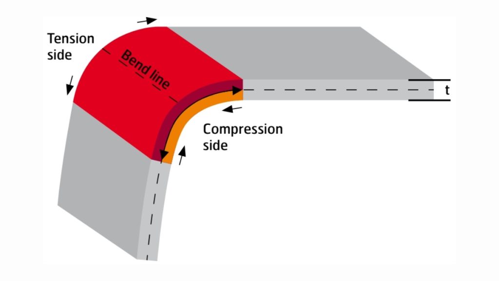
Minimum Bend Radius
Each metal possesses its minimum bend radius. You need to compute this by use of thickness and tensile properties. Its avoidance leads to cracking of the surface or uneven springback.
The red band radii of stainless steel may be more than 1.5 thickness. The more malleable alloys enable more compact radii but have a chance of deformation. Angles and material response to tooling dies have to be comparable.
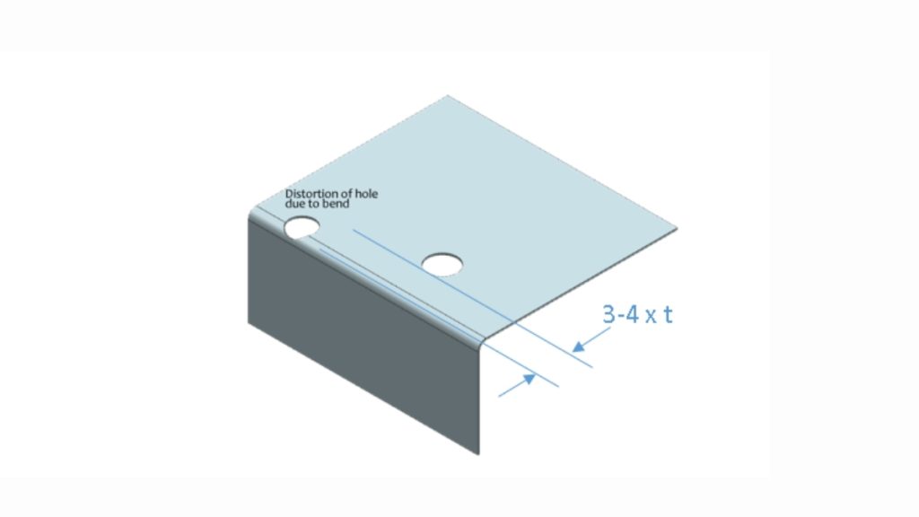
Hole Distortion In Bending
The strength and part integrity formed are affected by the hole location. Do not locate holes less than 2x the thickness of bends. The proximity placement is more prone to distortion during the brake procedures.
Punching close to the sheet edges also makes them vulnerable. So, you should provide enough clearance of features in hardware after pressing. Besides, the flatness of holes makes the fastener engage properly.
The tolerances must needs to be taken into account at the cut, bend, and join stages. Each aspect is added to the ultimate dimensional disparity. This leads to misaligned assemblies in the absence of stack-up management.
The welding may lead to the loss of flatness through thermal distortion. You will have to plan symmetrical or balanced layouts and forces. Additionally, warping is avoided by being careful with the way clamps are placed during forming.
The coatings influence the thickness, conductivity, and hole clearance. During powder coating, 60-80 microns are added; during anodizing, a few microns less. These changes have a place in precision assemblies or moving parts.
Around fastener areas and threads, it is usually necessary to mask. Mechanical tolerances should not be disturbed by pre-treatment. You only apply after final forming the finishes.
Geometries of components should be within the capabilities of fabrication. There can be sharp turns or reverses that could be beyond the braking tools. Strong metals need equivalent press tonnage settings.
Aside from this, enclosed features may need multi-stage tooling. The reach of the laser heads and the position of the punch dies have to be checked. Any unreachable areas should either be divided or re-planned.
Installation of fasteners has to take place on smooth, un-deformed material. Fastener spec hole dimension must conform within 0.08 mm. Mismatch creates a possible thread alignment or pull-through of the fastener.
You must consider the full hardware insertion sequence. Inserting before forming may distort holes under stress. Rivets, PEM studs, or standoffs all require calibrated press force.
Not all applications require sheet metal fabrication. It depends on volume, geometry, and performance. Other methods may suit better. Below are some alternatives to consider for specific use cases.
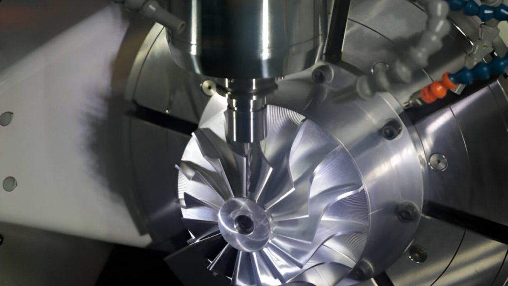
Precision CNC Machining
CNC machining entails the removal of material from solid billets. It is used for low-volume parts having complicated design and geometry. It provides more tolerances than the majority of sheet procedures.
Therefore, it is appropriate for thick-wall buildings and prototypes of structural enclosures. It, however, produces more waste and increased material expenses.
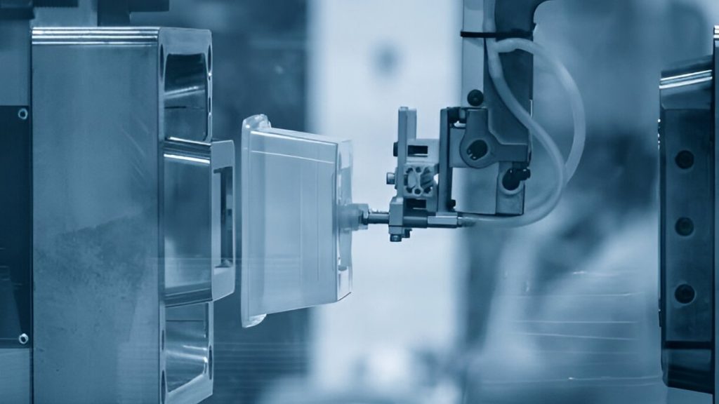
Injection Molding
Injection moulding is the perfect process to use when making large numbers of plastic components. You can achieve complicated tasks with no secondary forming. One of them is high tooling cost with low cost per unit.
You employ this where lightweight non-conductive housings or covers are used. But it does not have the thermal and structural strength of metal.
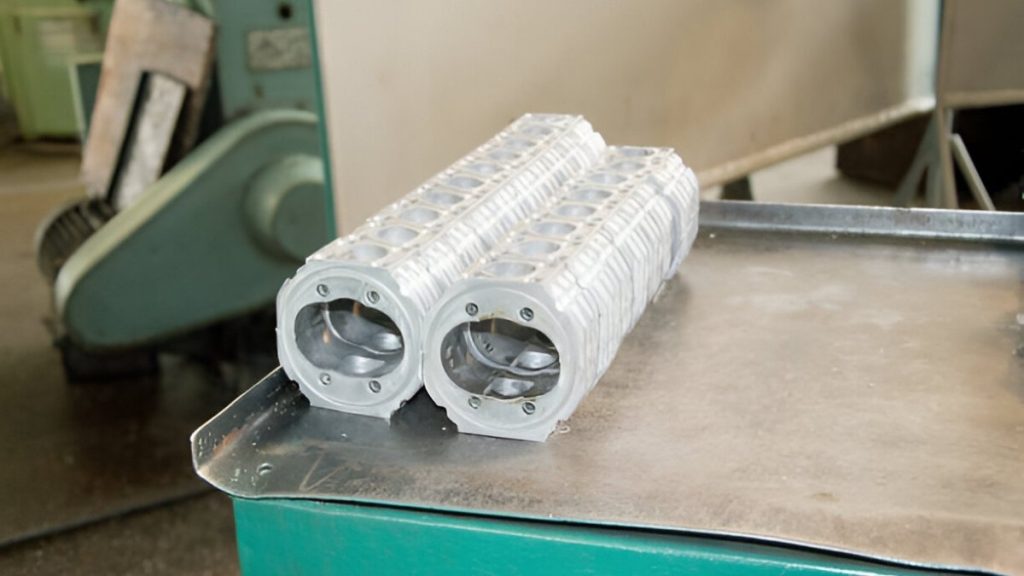
Aluminum Die Casting
Die casting forms metal parts using high-pressure molds. It is suitable for large-volume runs with complex, net-shape geometry. Common metals that can be die-cast include aluminium, zinc, and magnesium.
It’s ideal for housing or frames where surface finish matters. However, it requires expensive tooling and longer lead times.
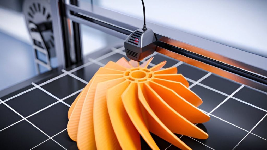
3D Printing
3D printing builds parts layer by layer. You use it for design validation and low-volume functional parts. Complex internal features are possible without tooling changes.
Metal and polymer options exist, depending on application needs. Tolerances and surface finish are limited compared to subtractive processes.
Precision sheet metal fabrication is a reliable method for producing complex, high-quality components. It enables you to maintain strict dimensional control, even across large production volumes. With the right setup, it delivers stable, repeatable outcomes for structural and aesthetic applications.
Every stage of the process requires careful planning. Material choice, bend allowance, hole positioning, surface finish, and fastener integration must align with equipment capability and part function. These factors determine how well your design transitions into a finished, usable part.
While alternatives such as CNC machining or injection moulding offer value in specific cases, sheet metal fabrication remains unmatched for flat or folded metal structures. When properly executed, it supports functional performance, efficient assembly, and long-term reliability in demanding environments.With our custom precision sheet metal services, ApexRapid help turn your designs into reliable, cost-effective parts for any application.

Laser Welding: Process, Effective Tips & Techniques for Optimal Welds

Metal Stamping Design: Process, Considerations & Useful Tips

Aluminum Heat Sinks: Process, Techniques & Applications

Aluminum Car Parts: Benefits, Techniques, and How to Source

CNC Medical Machining: Process, Techniques & Applications

Complete Automotive Machining Guide: From Discontinued Parts to Custom Solutions