Gears are the backbone of any machine. Yet the accuracy is a critical concern. If gear teeth are off by even a small amount, the system will vibrate, wear fast, and fail early.
Engineers often face issues like tooth profile errors, inconsistent backlash, and poor surface finish quality. These problems are usually caused by wrong tool selection, incorrect machine setup, and inappropriate cutting parameters.
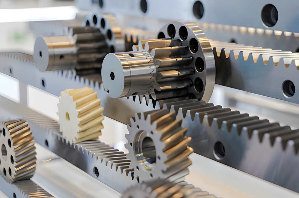
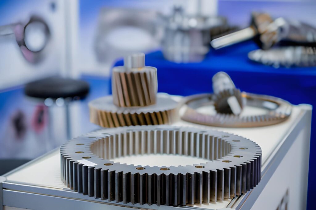
Precision Gears
CNC gear cutting solves these issues by offering precise control over tooth geometry, spacing, and surface quality. Modern CNC machines can cut gears with tight tolerances and high accuracy. This makes them ideal for high-performance applications like automotive transmissions, aerospace drives, and industrial gearboxes. However, the process still needs careful planning, correct tooling, and proper inspection to ensure success.
In this article, you will learn the process of CNC gear cutting. You will see the cutting methods and also learn practical tips for tool selection, machine setup, and quality control.
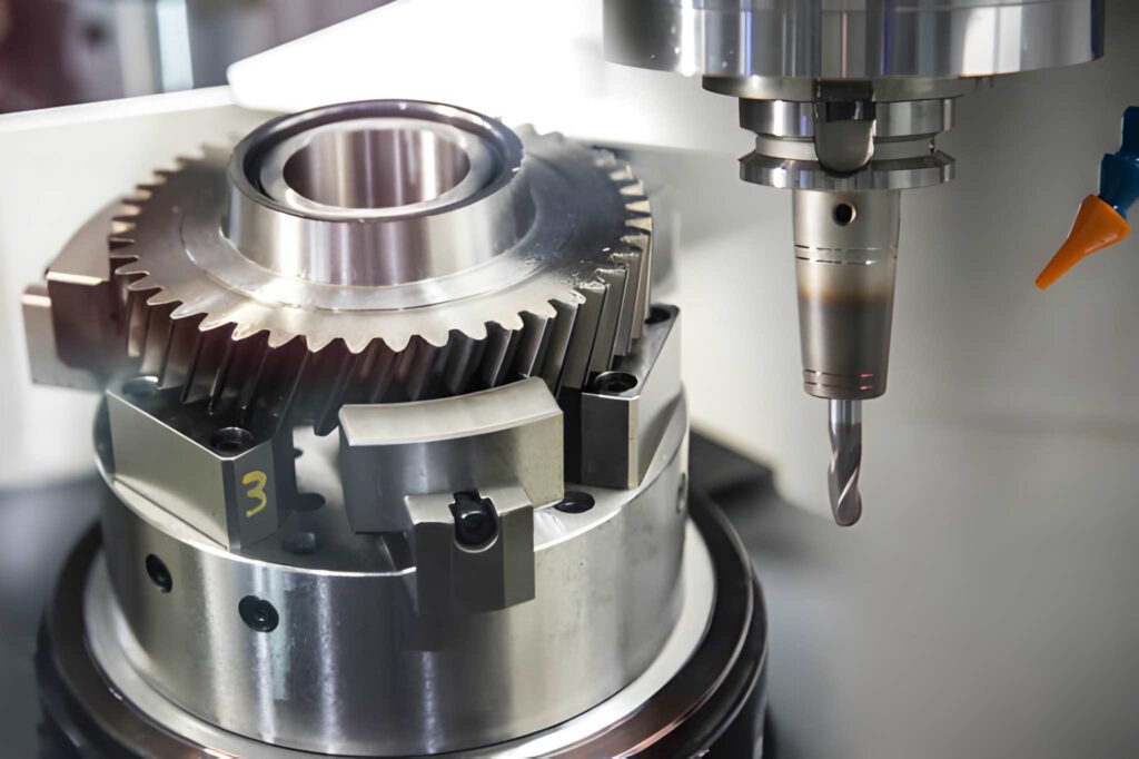
CNC Milling Machine Cutting the Sample Gear Part
CNC gear cutting is the process of producing gear teeth using computer-controlled machines. The machine follows a programmed path to cut the exact tooth shape, spacing, and depth. This method replaces manual gear cutting and older mechanical gear hobbing setups.
A CNC machine employs special cutters such as hobs, form tools, or end mills. These instruments cut the blank to form the gear profile. CNC gear cutting has the benefit of tight control of tooth geometry, backlash, and finish. It also facilitates reproducible delivery of the same gears, which is very critical in high-volume production.
CNC gear cutting has a systematic plan from design to inspection. The accuracy of the final gears and performance is influenced by each stage. A methodical operation minimizes scrap and enhances repetition.

Gear Technical Drawing
This begins by specifying the type of gear, module, pressure angle, and number of teeth. You ought to also set levels of tolerance of pitch, runout, and profile. This is one step that defines the gear's working capability and loading capacity. Its design must be according to the intended use and operation.
Choose the material based on its strength, wear resistance, and costs. Alloy steel, stainless steel, and aluminum are the most utilized materials. Heat-treated steel is recommended in case of high-load gears. Blank is then cut in size, faced, and centered to give uniformity, and then cut.
Select the appropriate cutter type, e.g., hob, form cutter, or end mill. Choose the cutter material according to the blank hardness. Next, specify the cutting parameters, including speed, feed, and depth of cut. The CNC program is designed with the aid of the data of gear design and the tool information.
Cut the blank and place it in a hard structure and position it accordingly. Adjust the machine to zero and verify the positioning of the axes. Checkthe common tool length. Cutting of teeth can be done properly to eliminate vibration and cutting errors.
Carry out the gearing cutting operation depending on the chosen procedure. Monitor tool wear and vibration. Monitor coolant flow to check temperatures and remove chips. Minimally adjusted when necessary to correct tooth profile or tooth spacing.
In case the gear entails high levels of strength, after cutting, the gear undergoes heat treatment. Typical processes consist of carburizing, quenching, and tempering. The wear resistance and load capacity are enhanced by the heat treatment. Heat treatment frequently calls for the finishing of gears to regain accuracy.
In the case of high precision gears, it is ground after cutting or heat treatment. The surface finish, noise reduction, and tightening of the tolerances are all enhanced through grinding. This is a critical step in aerospace and automotive gears, where accuracy is very important.
Read gear geometry with a gear measuring machine or CMM. Check tooth profile, pitch, backlash, and runout. Note the findings and compare them with design requirements. Only gears passing the standards are taken to the final assembly or shipment.
CNC gear cutting varies according to the type of gears, material, and accuracy requirements. Both methods have certain advantages and disadvantages. Selecting the appropriate approach allows the saving of time, minimization of costs, and enhances the work of gears.
The most popular process of spur and helical gears is gear hobbing. A hob cutter rotates around and shaves teeth when the gear blank rotates. Good surface finish and accurately cut tooth profiles are obtained by this method. It is effective in medium-volume to high-volume production.
Gear shaping suits well with small external gears and internal gears. The blank drops and cuts together. Shaping is less fast than hobbing, though more accurate, and has more control of complicated profiles. It is also convenient in tight spaces, unlike other procedures.
Gear milling involves cutters that are used to cut gear teeth with form cutters or end mills. It applies to prototypes and low-volume production. Milling is versatile, and it can be changed to change gears in a short time. It is, however, not efficient and slow in large batch production.
Gear grinding applies to high-precision gears and hardened metals. It comes after gear cutting to enhance accuracy and surface finish. Tight tolerances and low noise levels can be attained by grinding. It is vital in aerospace, automotive, and high-speed applications.
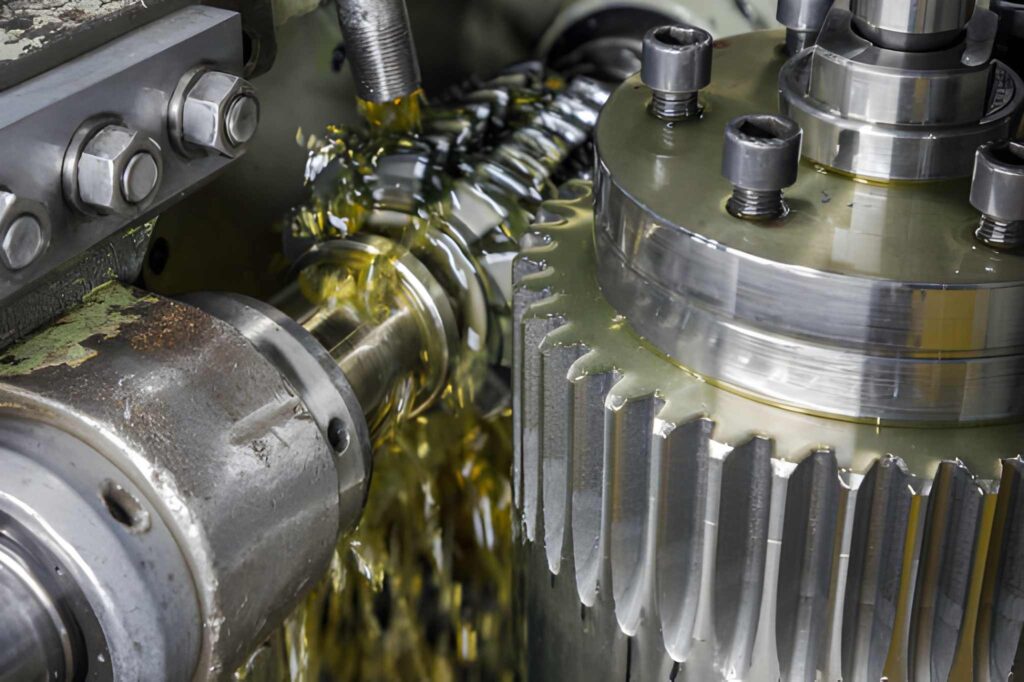
Gear Hobbing Machine
Internal gears and splines are skived using gears. The procedure is cut with a rotating cutter at an angle. Skiving requires more time than shaping and applies to small to medium internal gears. It is particularly applicable in hard materials and complicated contours.
CNC gear cutting does not appear complicated, yet it has actual technical difficulties. The problems directly influence the accuracy of the gear, noise, and longevity. Their handling by the engineers should be taken into consideration during design and production.
Tooth profile errors occur when the machine calibration or path cutter is in error. A misalignment of 0.02 mm may add noise and wear. Backlash problems occur when there are errors in the gear spacing. This causes loose gear mesh and premature breaking.
Gear cutters are worn quickly, particularly on hard materials. Worn cutters alter the shape of the teeth and make them rough. This will lead to increased friction and reduced efficiency. Frequent check-ups of the tools used and replacing them in a proper manner are necessary.
The cutting process produces heat in the tool and gear blank. The gear is distorted and expanded by heat. Bent gears are not going to fit correctly, and they will come lose at load. Harmless coolant and regulated cutting rates lowerthe heat influences.
Gears with a high count of teeth create many chips during cutting. Uncleared chips lead to damage to tools and marks on the surface. Burrs occur at tooth edges, which necessitate additional deburring procedures. Adequate flow of coolants and evacuation of chips are important.
Gear cutting entails a high level of accuracy in the positioning of the cutter and the blank. Any lack of alignment will result in uneven tooth setting and irregular quality of gears. Before production, one has to verify the machine arrangement by testing it with test cuts and inspection tools.
Good planning, proper tooling, and a stable setup are the first steps to effective gear cutting. Minor adjustments in arrangement can enhance equipment precision and minimize wastage. Some useful advice that engineers adopt in actual manufacturing has been provided below.
Most spur and helical gears are selected, hobbed. Internal gears and tight spaces should be shaped with use. Select hardened gears with grinding and high accuracy. Corresponding the method to the type of gear decreases rework and enhances uniformity.
Apply carbide or high-speed steel cutters depending on the hardness of the material. Diamond or CBN grinding wheels are to be used where hardened gears are concerned. Tool geometry and edge quality must be checked before cutting. The tooth errors can be avoided due to the proper choice of tools and a better finish.
Begin at safe speeds and start to increase only in case the gear and tool are stable. Speed causes heating and distortion. The speed is too low, resulting in rubbing and a poor finish. Apply feed rates, as suggested by tool suppliers.
Rigid clamping and proper centering are to be used in order to avoid vibration. Tooth spacing and surface quality are sensitive to any type of movement. Check compliance through test cuts and measurement equipment before full production.
Apply either flood coolant or mist cooling to regulate heat and rinse chips. With high tooth count gears, it is important that it does not trap chips between teeth. The trapped chips cause destruction of the tool and gear surface. Proper flow of coolant enhances tool life and finish.
Measure tooth profile, pitch, and runout using a gear measuring machine or CMM. Mistakes are found before full production. This saves time and removes scrap due to wrong settings.
Many industries require gears that are machined using CNCs in order to achieve precision and strength. These gears have to work in high loads, high speed, and long working hours. CNC gear cutting is preferred by engineers who are concerned with the accurate tooth profiles and performance.
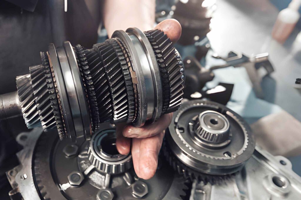
Cross-section of a Car Gearbox
Cars and trucks have transmission systems that make use of CNC gears. These gears will have to deal with high torque and cyclical loading. Accurate tooth design minimizes noise and enhances productivity. This is normally applied to hardened and ground gears.
The gears in aerospace are in high-tolerance and need to perform smoothly. Flight control systems and actuators are accurate because of CNC machining. The gears are usually made of lightweight metals such as titanium and aluminum.
Spur and Bevel Gears
CNC gears are used in industrial gearboxes to supply the desired motion and control of torque. Robots require high precision and reproducibility. The process of cutting gears with CNC technology guarantees uniform tooth location and movement.
Small precision gears are used in medical devices in pumps, imaging, and surgical equipment. These gears must be very precision-oriented and produce low noise. Gear cutting CNC offers the control necessary in such applications.
Gearboxes of wind turbines require robust gears capable of contending with changing loads and extended service. Tolerance and durability requirements can be met with the assistance of CNC machining. High reliability of these gears usually calls for the process of grinding and finishing.
If you need reliable CNC gear cutting, we can help. We handle gear design, cutting, heat treatment, and finishing. Our team works with steel, stainless, and aluminum, and we support both small and large batch runs. We also provide quality inspection using CMM and gear measurement tools. Send your drawing and requirements, and we will review them quickly. Get a quote today and start your gear production with confidence.
What gear types can you cut?
We cut spur, helical, bevel, and worm gears. We also handle internal gears and splines.
What tolerances can you achieve?
Typical tolerances are ±0.05 mm. For critical gears, we can reach ±0.02 mm with grinding.
What materials do you work with?
We work with alloy steel, stainless steel, aluminum, and bronze. We also handle hardened gears.
Do you offer heat treatment and grinding?
Yes, we provide carburizing, quenching, tempering, and gear grinding. We also handle finishing and inspection.

Laser Welding: Process, Effective Tips & Techniques for Optimal Welds

Metal Stamping Design: Process, Considerations & Useful Tips

Aluminum Heat Sinks: Process, Techniques & Applications

Aluminum Car Parts: Benefits, Techniques, and How to Source

CNC Medical Machining: Process, Techniques & Applications

Complete Automotive Machining Guide: From Discontinued Parts to Custom Solutions