To achieve a top-notch surface look and make parts right for milling is key in CNC Milling work. While rough steps remove a lot of material, the finishing step is where exact size, true shapes, and good looks come alive, and with the help of design for manufacturability (DFM) ideas early, It can be make sure parts can be made well, cheaply, and with the look you want. This tutorial will explore the tips and tricks you need to know to get your CNC-milled parts just right, including toolpath planning tricks and post-machining operations.
The Importance of Finishing
The final surface finish of a CNC-milled component directly influences the functional use, fit, and aesthetic appearance of a part.
Work Use: A smoother face can cut down on rubbing and wear between parts, better fluid flow, or make a good seal
Dimensional Accuracy: Because finishing passes are generally light ones, the machine can be held to tighter tolerances and can therefore produce the desired dimensioned size of a design.
Looks: For products you see or parts that show, a good finish is key for how people see the quality, and for making buyers happy
Post-Work: Many face care steps, including anodizing, plating, or painting, require a certain roughness to bond well and give a better look.
The importance of Design Guidelines
It is effective to design with CNC milling taken into account from the very beginning to save time, material, and cost.
Optimized Machinability: Guides can be used to generate geometries that are easy to reach and cut with a milling tool, shortening machining time and tool life.
Lower Cost: Simpler designs with fewer steps, common tools, and doable sizes lead to much lower manufacturing costs.
Better Quality: Plans for steady and stiff designs lower chatter and bending, resulting in a better surface and true sizes.
Fewer Changes: Using plans to cut down on the need to redo designs due to disruptions, making the process smoother.
Using Materials Well: Smart design can mean less waste, which is key for pricey materials.
Knowing Surface Finish in CNC Milling
Surface finish, the texture of a surface, is quantified by surface finish, which is commonly evaluated in terms of surface roughness (Ra). To attain the sought-after finish requires understanding its determinants.
Defining Surface Finish (Ra)
Surface Roughness (Ra - Roughness Average) is the average of the up and down from the middle line. A lower Ra means a smoother face. Usual units are micro-inches ($\mu$in) or micrometers ($\mu$m).
Mirror Finish: Gets Ra as low as 1μin (0.025μm), often needs polishing.
Fine Finish: 8−32μin (0.2−0.8μm), can be done with the right ending steps and tools.
Normal Machined Finish: 63−125μin (1.6−3.2μm), usual for non-key faces after common milling.
Things That Affect Surface Finish
Many things directly affect the final appearance. Knowing these lets you control it well.
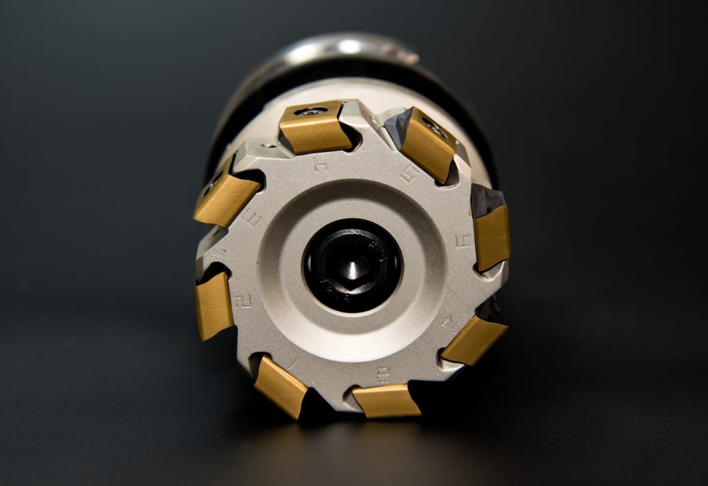
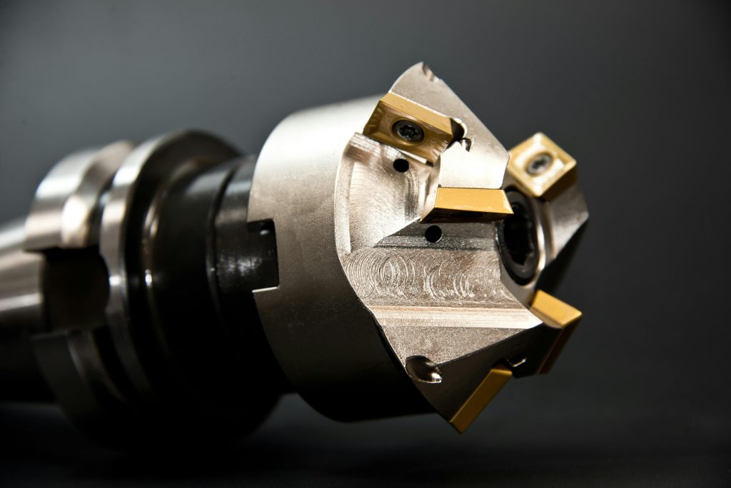
Parameters of Cutting Tools
Tool Shape: Sharp cutting sides are key. Tools for finishing (e.g., with higher flutes, certain helix angles) keep material tearing low.
Tool Material: Carbide tools often have better finishes than HSS because they get stiff and stay sharp at high speeds.
Tool Coating: Coatings TiN, AlTiN (for steel), or TiB2 (for aluminum) reduce friction, prevent edge build-up, and facilitate chip removal, all contributing to a superior finish.
Runout: To keep tool runout (wobble), all flutes must share the same cutting load. Good tool holders (shrink-fit, hydraulic) lower runout.
Tool Diameter: Tools with larger diameters, where feasible, can occasionally permit higher stepovers with acceptable scallop height or permit more secure cutting.
Machining Parameters
Spindle Speed (RPM): As spindle speed is increased, RPM tends to produce a better finish, and the peak-to-valley height of the individual cutting marks is decreased.
Feed Rate (IPM): Lower feed rates (or chip load per tooth) usually give better finishes. Too slow, though, may lead to rubbing and more heat.
Depth of Cut (DOC) / Stepover: lighter axial and radial depths of cut during finishing passes help reduce tool deflection, cutting forces, and produce finer surface textures.
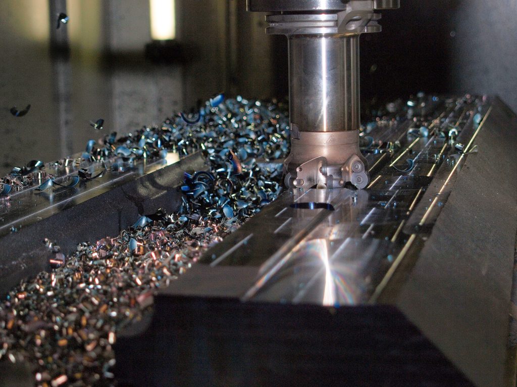
Chip Evacuation: Efficient chip clearing stops chips from being cut again, which can dent the surface. Coolants or air help a lot.
Coolant/Lubrication: The right coolant or lubrication reduces friction and heat at the cutting area, stops BUE, and improves the face quality.
Machine Firmness: A strong machine with minimal vibration and play is key for tight sizes and fine finishes.
Material Properties
Material Hardness: Harder materials often require slower speeds and lighter cuts, which affects the finish.
Ductility/Gummy Materials: Softer, more ductile materials (e.g., pure aluminum, some stainless steels) are prone to BUE and tearing, making it harder to achieve a smooth finish.
Grain Build: The grain build of the material is a very determining factor of the machined surface.
Best Practices for a High Quality Finish
The combination of Specific tool selection parameters, programming, and machine operation allows achieving a high-quality surface finish in CNC milling.
Tool Selection for Finishing
Choice of Tools to Use in Finishing
Ball Nose End Mills: Perfect for 3D-shaped surfaces. The smaller the ball, the more detail, but the longer it takes.
Corner Radius End Mills: These are stronger than square end mills and leave a tiny radius in corners, looking better and stronger.
High-Flute Count End Mills: For flat or profile end jobs, using 4-6 flutes (for steel) or 3 flutes (for aluminum) gives a finer finish with more cuts each turn.
Compression End Mills: Applied in finishing thin sheet materials in which the top and bottom surfaces require a clean cut.
Burnishing Tools / Roller Burnishing: Instead of cutting, these tools press and smooth the surface, often reaching very low roughness levels.
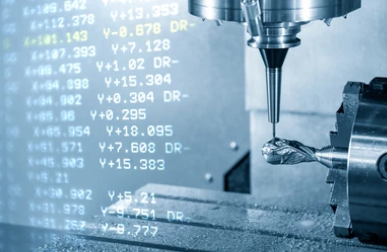
Finishing Toolpath Strategies
The CAM software offers different strategies based on geometries and planned finishes.
Contour Machining: Follows the part's profile. Climb milling is generally preferred for finishing as it provides a better surface finish, evacuates chips away from the cut, and puts less stress on the tool.
Parallel Passes (Raster): Used for flat or slight slope surfaces, moving the tool in back-and-forth lines.
Scallop Height Control: For 3D surfaces with ball-nose mills, CAM software lets you set the top scallop height, which controls surface roughness. Smaller scallop height = finer finish.
Spiral/Morph Toolpaths: Gives a steady finish on complex shapes by spiraling in/out or changing to match the part's shape.
Rest Machining (Remachining): Rest machining uses smaller tools to clean parts, ensuring a consistent finish in tight spots or small details.
Optimisation of Finish Machining Parameters
It is critical to fine-tune your speeds and feeds.
Higher Spindle Speed (RPM): Lowering chip thickness and enhancing chip formation can be achieved by higher spindle RPM.
Lower Feed Rate (IPM) / Chip Load (IPT): Cutting less material per tooth usually leads to a smoother surface. But, don't go too slow, as it may cause rubbing.
Light Depth of Cut (DOC) / Stepover: Light cutting depth of cut (DOC) (down to 0.005"-0.020" or 0.1 mm- 0.5 mm) and small stepovers (down to 5-15% of tool diameter on flats, and much less on 3D shapes) are commonly used on finishing jobs.
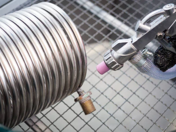
Constant Coolant Usage: It is recommended to use coolant to maintain the temperature control, aid in chip escape, and oil the cut, preventing any buildup and enhancing the surface finish.
Minimal Tool Extension: It is also recommended to use a minimal tool extension from the holder to reduce shaking (chatter).
CNC Milling Design Guidelines
It is considered crucial to design components that are efficiently and excellently CNC milled, otherwise known as Design for Manufacturability (DFM). Incorporating them at the very beginning of the process makes production easier and cheaper.
DFM General Principles
These are general to any milled part.
Keep Shapes Simple: Do not use hard shapes if you do not need to. Simple shapes mean less work for tools, set-up, and code writing.
Use Common Tools: It is recommended to machine parts that use tools one can find easily (standard-sized end mills). Rare tools take more money and time.
Right Tolerances: Only use tight measures (like ±0.0005"/±0.01mm) if needed. Tight measures take more time and money. Loose ones (like ±0.005"/±0.1mm) work well most times.
Wall Size: It is recommended to use walls that are thick to stop deflection and chattering. A good rule is 0.040" (1mm) for aluminum and 0.060" (1.5mm) for steel. It depends on the part size.
Space for Tool Holders: Always consider clearance for holder sizes when making deep parts or those near clamps.
Design Considerations by Part Features
There are distinctive features of parts that are advantageous through customized design.
Internal Corners & Pockets
Radii are Your Friend: internal corners in milled parts will never be sharp, but will be rounded to the radius of the cutting tool. To allow clearance of the tool and to avoid over-machining, design such radii a little larger than the tool you intend to use. Internal sharp corners (90 sharp edges) should be avoided.
Fillet Depth: Make sure the curve goes deep enough for the tool to reach all of the corners.
Pocket Depths: Pockets that are deep and thin are hard to make. They need long, slender tools that are susceptible to deflection and vibration. A shallower pocket design or through-hole should be offered where possible. When deep pockets are inevitable, think relief corners at the bottom.
Holes & Threads
Use common hole sizes: Device hole sizes that fit standard drill bits to cut the costs.
Hole Depths: Holes deeper than five times their width (e.g., Depth > 5x Diameter) are hard to make right. They also make it hard to get rid of the bits that come off. Think about through-holes or made in several drilling movements (peck drilling).
Thread Design: Pick threads that people use a lot (e.g., M6x1.0, 1/4-20 UNC). Say how deep the thread should go. For holes you can see through, keep the depth no more than 2.5 times the width. For holes that end, keep it to 1.5 times. This makes the threads strong. Also, ensure clearance at the bottom of blind tapped holes.
Undercuts & Hard Shapes
Do not make undercuts: Machines that mill with three axes can't make undercuts (parts needing the tool to cut up from below or sideways into a blocked spot). If you need this, consider using machines with more axes, setting up the part several times, or changing the design.
Accessibility: From a standard setup, it is recommended to ensure that the tool can access all the surfaces to be machined.
Angles in the cut: Unlike with molding, you usually don't need angles for milling with a CNC machine, unless it's for special mold holes.
Part Features and Stability
Thin walls: Make walls thick enough to stop shaking and bending when cut. Add ribs or support if thin walls can't be helped.
Flatness: For big, thin parts, think about adding ribs or taking some material off here and there to keep it flat and stop it from bending out of shape later.
Edges - Chamfers vs. Radii: It's usually simpler and quicker to make beveled edges than rounded ones for outside corners.
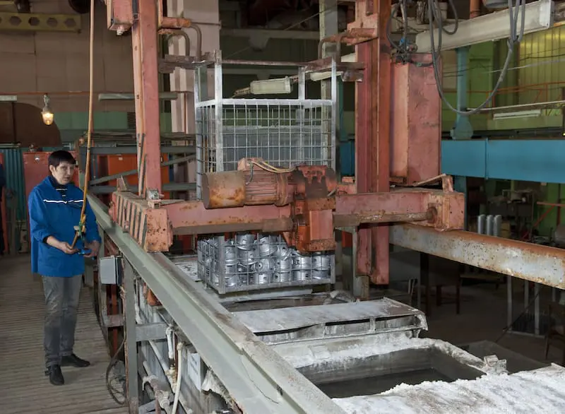
Post-Processing & Finishing Touches
After machining, a range of post-processing operations is employed to improve the part finish, appearance, and functional characteristics.
Deburring
Removing sharp edges (burrs) created during machining is a crucial step for safety, functionality, and aesthetics.
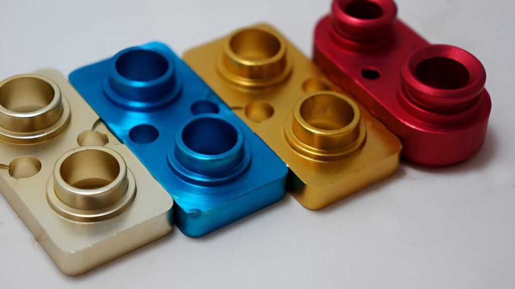
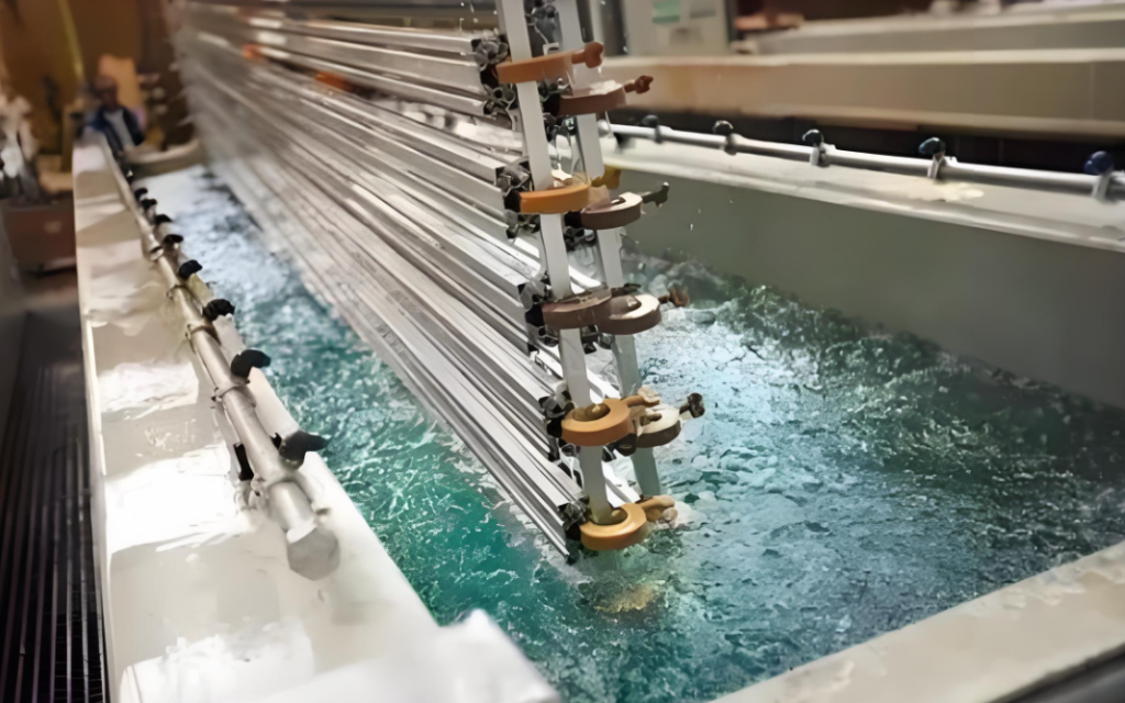
Surface Treatment & Coating Choices
These steps can hugely change how the part looks and lasts.
Anodizing (for Aluminum): Makes a tough, lasting, often colorful oxide layer.
Type II (Sulfuric Acid): For more uses, it can be in many colors
Type III (Hardcoat): Thicker, harder, for intense wear (colors limited, often dark grey).
Powder Coating: A lasting, colorful finish is put on with static and then baked. Good against chips and scratches
Painting: Adds looks and some shield.
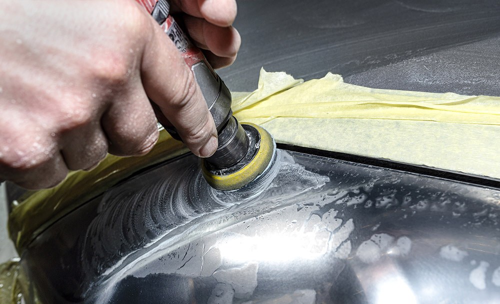
Polishing/Buffing: Makes a shiny, mirror-like surface by rubbing.
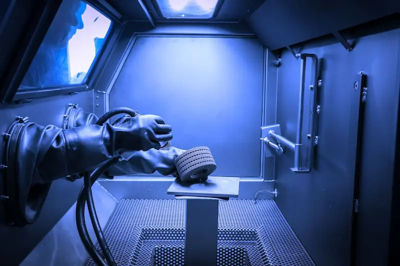
Bead Blasting/Sandblasting: Sandblasting/Bead Blasting provides a good matte or satin finish, hiding minor machining marks and providing a good base for other coatings.
Electroless Nickel Plating: Electroless nickel plating provides a uniform, corrosion-resistant, and hard coating on different metals, even aluminum (with appropriate pre-treatment).
Passivation (for Stainless Steel): On the surface, it removes free iron and passivates to give natural corrosion resistance with no visible coating.
Finish Quality Inspection
Checking the quality of the finish is as important as the machining itself.
Visual Check: First, look for big flaws, tool marks, or uneven spots.
Surface Roughness Testers (Profilometers): Tools that measure Ra and other surface finish details right on the piece.
Optical Comparators / Microscopes: Used to look closely at surface feel and small details
CMM (Coordinate Measuring Machine): To confirm machining accuracy, high-precision CMM machines are used for dimensional verification.
Conclusion: Designing Accuracy and Perfection
CNC milling design and finishing guidelines are built on years of hands-on experience. They elevate your machining results from basic functionality to true precision. Achieving high surface quality and accuracy requires careful coordination of tool selection, machining parameters, and design intent. At Apex Rapid, we specialize in precision CNC machining to help you turn complex designs into high-quality parts with confidence
FAQs
Q1: What is the most severe parameter in the attainment of a good surface finish in CNC milling?
A1: Correct tool selection and adjusted parameters, in other words, sharp tools, light cuts, high RPMs, and good chip/coolant management.
Q2: Why would I worry about putting radii in the inside corners of my design?
A2: Radius corners facilitate tool entry, minimize wear, accelerate machining, and enhance part strength through corners by decreasing stress.
Q3: What is climb milling, and why is it a better choice in finishing?
A3: Climb milling provides a cleaner cut, a better finish, chips are thrown away, and it saves tool wear and stress.
Q4: I have thin walls that are vibrating when machining, resulting in a poor finish. What can I do?
A4: Minimize cutting forces, enhance rigidity, shorten tools, use adaptive toolpaths, or provide support in design.
Q5: What are the guidelines for deciding on various post-processing methods such as anodizing, powder coating, and bead blasting?
A5: Make the decision based on appearance, precision, and durability; anodizing precise, powder coating tough, bead blasting textured.