Metal stamping design has a direct impact on part quality, tool life, and production cost. In many cases, problems do not start on the press floor. They start much earlier, at the design stage. Sharp corners, unsuitable materials, tight tolerances, and poor bend planning often cause cracking, springback, or fast die wear. These issues slow down production and increase scrap and rework.
A well-thought-out metal stamping design helps avoid these problems before manufacturing begins. When part geometry matches material behavior and press capabilities, forming becomes more stable and predictable. Proper design reduces stress in critical areas, protects tooling, and supports consistent high-volume production. It also shortens setup time and lowers overall manufacturing cost.
In this article, we will walk through metal stamping design from a practical, manufacturing-focused view. We will discuss material selection, feature design rules, bend and tolerance planning, and common design mistakes engineers face.
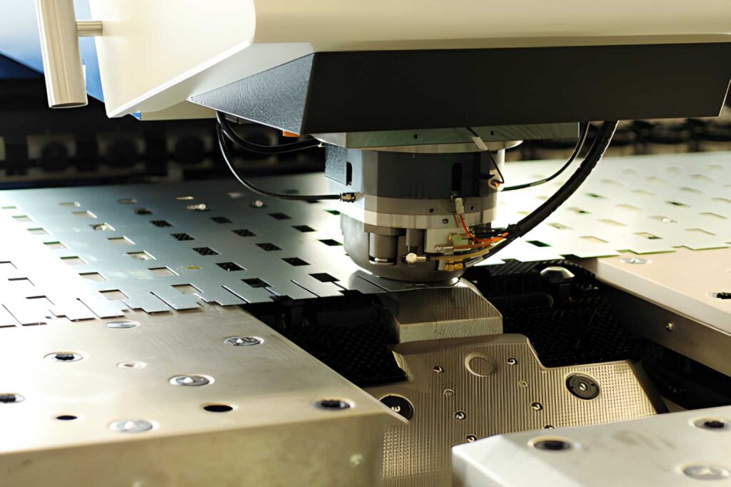
Sheet Metal Stamping
Metal stamping design is the process in which a part is designed to fit in a stamping press and die, not to oppose it. It specifies the way in which a sheet of flat metal will be cut, bent, or shaped without cracking, wrinkling, or too much springback.
The design is concerned not only with the final part shape, but with the real forming behavior. Pragmatically, the design of metal stamping implies the correct amount of bend radius, the distance of holes to bend lines, material flow during stamping, and the choice of tolerances of the press. It also takes into consideration material thickness, grain direction, and die clearance. When these parameters are managed well, production runs smoothly, the die lasts longer, and you need fewer adjustments after pressing.
Processes and Steps for Die Stamping
The design of metal stamping is a coordinated procedure of planning a part in a way that it can be manufactured with a stamping press and die. The aim is to achieve a part to be precise, robust, and simple to manufacture. When the design is correct, the part will run easily in production and will be in tolerance.
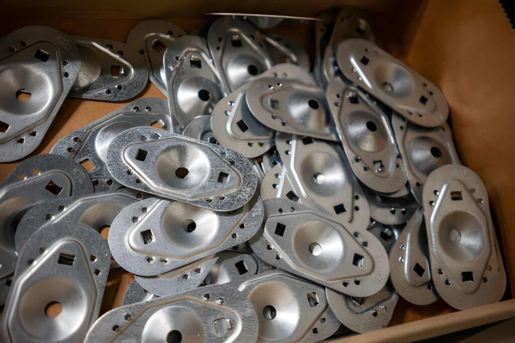
Aluminum Stamped Parts
The first thing is to select the appropriate material and thickness. It is not merely a question of power. It influences the way in which the metal would bend, stretch, and rewind. As an illustration, the stainless steel requires additional pressure and can crack when the design is not sharp enough. Aluminum is more readily formed, but may wrinkle. Early choice of material eliminates problems in the future.
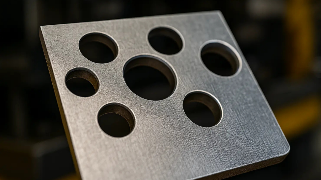
Stamped Holes
The next step is shaping the stamping part. You do not touch sharp corners since they crack. You do add the right radii and take sufficient distance between features. As an illustration, a hole that is too near a bend will shatter in the course of shaping. It is the step in which the greatest number of failures occur, and therefore, good geometry saves time and scrap.
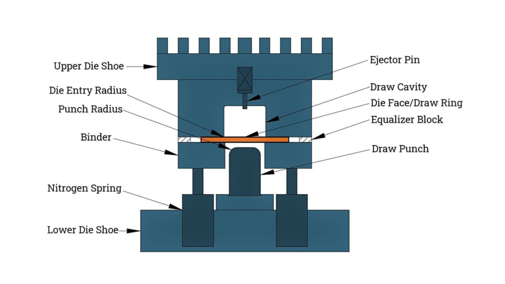
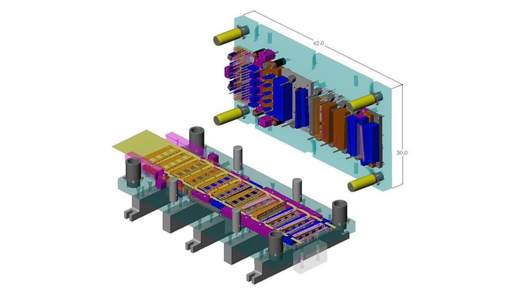
Stamping Die design
The design makes your part become a tool. In this case, you would determine what type of die, clearance, and the flow of material. Clearance should be equal to the thickness of the material. Excessive tightness and excessive looseness elevate tool wear and result in poor edges, respectively. A smart die design minimizes tool wear and holds the component in check.
Then you chart out the course of action. Stamping can begin with blanking and piercing. Later, there is bending and forming. In case you attempt to create complicated features at the start of it, the metal may rip. An appropriate order enhances quality and scrap.
Tolerances have to be equal to what stamping will give. When you demand a very high tolerance, manufacturing will not be at ease. You have to work on springback, too. This is the propensity of this metal to flow following a bend. It must be compensated by the die. The correct tolerance planning lessens the rejection and enhances consistency.
Lastly, you are cost and efficiency-driven in the design. An ideal design minimizes the cycle time, scrap, and tool wear. In high-volume production, it is worth having a more complex die. In small production, simple tooling is retained. An efficient design maintains the cost to a minimum and the quality of the part to maximum.
The incorrect design of a metal stamping leads to scrap, damage to tools, and delays in production. It has an influence on fit, finish, and part strength. The majority of the problems are caused by bad selection of materials, wrong tolerances, and poor die layout.
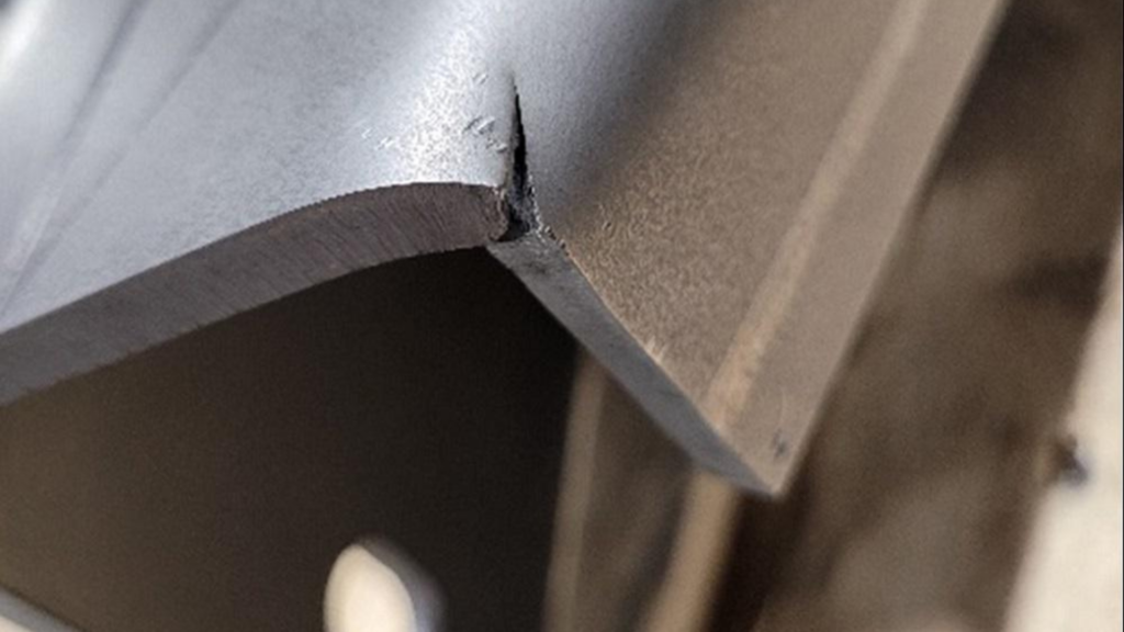
Edge Cracking in Sheet Metal Part
When the design contains sharp corners or is thin, the metal breaks when it bends. The most prevalent failure is this. The component might appear good, but following the initial few cycles, cracks will be visible. This wastage of time and material.
Wrinkling occurs when the metal of the die is excessively loose or when the design contains excessive material in one section. During forming, buckling may take place in the event that the part is not supported. The two problems render the part useless and scrap it.
Bad die layout or wrong clearance augments tool stress. Tools become duller and more corroded earlier. This leads to low-time and high tooling expenses. Poor design also translates to higher maintenance of the tools.
If the part geometry is not designed for stamping, the tolerance becomes inconsistent. The section might not fit or fit together. This results in rework and delays. The end product can be of poor quality.
Poor design increases cycle time, scrap, and tool changes. This raises the cost per part. Even minor design flaws may prove costly when doing large volumes of the run.
The part will not be in the right shape after bending unless springback is taken into consideration. This leads to improper angles and improper fit. The die should be changed or redesigned.
Metal Stamped Parts
A good design minimizes wastage, enhances quality, and saves time. It simplifies the production process.
Cracks, wrinkles, and misfeeds are eliminated by good design. This ensures that there are reduced rejected parts and material wastage. Your manufacturing is cleaner and more efficient.
When the design is correct, the part flows out of the die. This minimizes the cycle time and enhances production. It is capable of hitting higher volumes at no additional expense.
Proper clearance and die pattern minimize the stress on tooling. This prevents the premature wear of tools or their breakage. There is an enhancement in the life of tools, and there is a reduction in the maintenance costs.
With an appropriate design, repeat accuracy is guaranteed. Components are standard dimensioned and fit. This minimizes the rework and enhances assembly success.
The best design facilitates the rightful flow of materials and bending. This leads to the production of superior components that are more durable. The finished product works better in the actual application.
Less scrap, fewer downtimes, and tool changes translate into less cost per part. An effective design increases productivity, as well as money in the future.
Metal stamping design should be in correspondence to part functionality, material capacity, and press capacity. In case one of them is erroneous, the component will not pass through the production process. The major considerations are discussed below, and they are the technical values that engineers apply in their everyday lives.
Stamping is mostly done with 0.3 mm to 6 mm thick steel. The common range of aluminum is between 0.5 mm and 4 mm. In case of excessively thin thickness, tearing occurs. When excessive, it takes more tonnage and tool stress to shape.
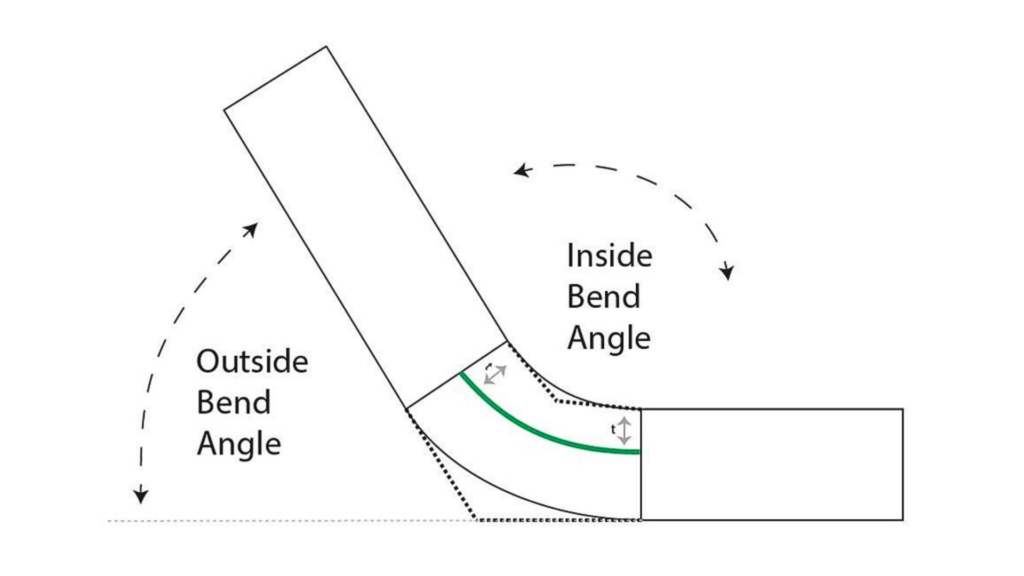
Springback factor on the press brake
The best rule is to have a bend radius of 1x to 2x of material thickness. In case of hard materials, 2x thickness should be used. Predict 0.5 ° to 3 ° springback per bend, depending on the material. This has to be countered in the die.
Maintain a minimum of 2x bend and edge thickness. This eliminates tearing and distortion in the course of forming. In the case of critical holes, retain a 3x thickness distance.
Die clearance typically is between 8 and 12 percent of the material thickness of mild steel. For stainless steel, use 10% to 15%. Burrs, high punch force, and early tool wear are the results of wrong clearance.
Whenever possible, grain direction ought to follow the line of bend. The Tilting across the grain increases the risk of a crack. It is of greatest concern for aluminum and high-strength steel.
In single-stage deep draws are required to remain less than 2x the diameter of the blank. In case you want to be more detailed, apply several drawing steps. Otherwise, you will find wrinkles and rifts.
The common stamping tolerances include +/-0.1 mm non-critical features. When correctly tooled, critical features can go to +/-0.02 mm. With tight tolerances, die accuracy is more stringent, and frequent inspection is necessary.
Finding a reliable metal stamping fabricator starts with knowing what you need. You desire a store that is capable of dealing with your material, geometry, and volume. The appropriate fabricator will also contribute towards the minimization of cost, delay elimination, and enhancement of the quality of parts. The following are some steps that you may take in practice.
Specify your material, thickness, and tolerance requirements before you search. Enter the part volume and the demand for either progressive dies or simple stamping. Otherwise, the fabricator may provide a quote for the incorrect process or machine. Specifications are time and cost-saving.
Inquire about their type of press and die. As an illustration, tonnage presses with a thickness of parts exceeding 3 mm require extra tonnage power. Multi-stage forming or powerful dies are required in complex components. When the shop does not have the correct press, your component will fail or have to be re tried again and increase the cost.
An honest fabricator ought to provide a reference to similar components that they made. Request case study, drawings, or photographs. They will know springback and forming limits as long as they have worked on your type of material and tolerances previously. Experience minimizes surprises in production.
The quality control should be equal to your tolerance requirements. Question of whether they are using CMM, height gauges, or optical comparators. Determine whether they have in-process checks and final inspection. The stores with the tracking of defects and SPC tend to produce steady results.
A reliable fabricator responds fast and explains timelines clearly. Questions to ask include tooling lead time, set-up time, and anticipated production schedule. Effective communication eliminates time wastage and assists in scheduling assembly or delivery.
An excellent fabricator offers transparent pricing of tooling, arrangement, and per-part expense. They ought to give reasons as to why the prices may be high in case the component is complicated. Open pricing is devoid of surprises and instills confidence.
If you need accurate metal stamping parts, we can help. Our team handles part design, die development, and full production. We work with steel, aluminum, stainless steel, and more. You get reliable stamping, consistent quality, and on-time delivery.
Send us your drawings and requirements, and we will review them quickly. We will also suggest design improvements to reduce cost and improve manufacturability. Get your quote today and start production with confidence.
What material thickness can you stamp?
Most shops handle 0.3 mm to 6 mm. For thicker parts, we use heavier presses and stronger dies. Material choice affects tool life and forming limits.
How tight can stamping tolerances go?
Typical tolerances are ±0.1 mm for normal features. Critical features can reach ±0.02 mm with precise dies and inspection. Tighter tolerances need stronger control and inspection.
What causes cracks during stamping?
Cracks happen when the bend radius is too small or the material is too hard. Grain direction and springback also matter. Proper radius, tooling, and forming strategy prevent cracking.

CNC Gear Cutting: Process, Techniques & Effective Strategies

Laser Welding: Process, Effective Tips & Techniques for Optimal Welds

Aluminum Heat Sinks: Process, Techniques & Applications

Aluminum Car Parts: Benefits, Techniques, and How to Source

CNC Medical Machining: Process, Techniques & Applications

Complete Automotive Machining Guide: From Discontinued Parts to Custom Solutions