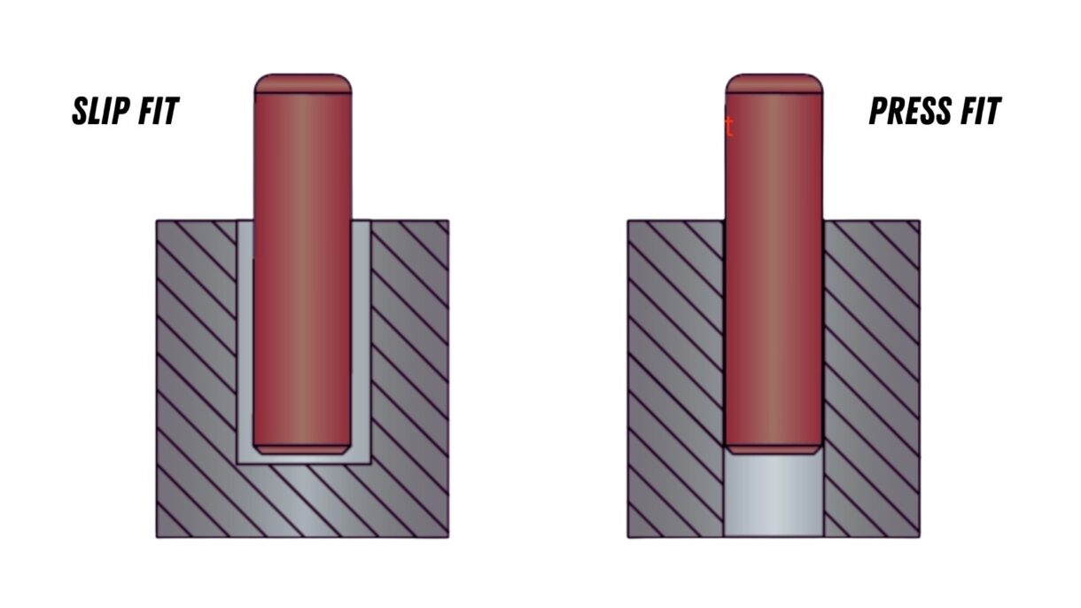
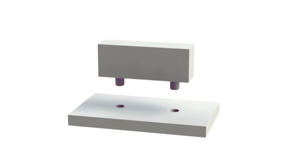
Press fit and slip fit are two common ways to join parts precisely. They involve fitting a shaft into a hole. However, they work differently. The key difference is how tightly the parts hold together and whether movement is allowed.
A press fit creates a tight, permanent connection. The shaft is slightly bigger than the hole. When you press the parts together, they lock firmly in place. This type of fit is used when you need strength and no movement between parts.
On the other side, a slip fit leaves a small gap. The hole is just a bit larger than the shaft. This lets the parts slide together easily with little effort. Slip fits are useful when parts need to move, rotate, or be taken apart for maintenance.
Press Fit
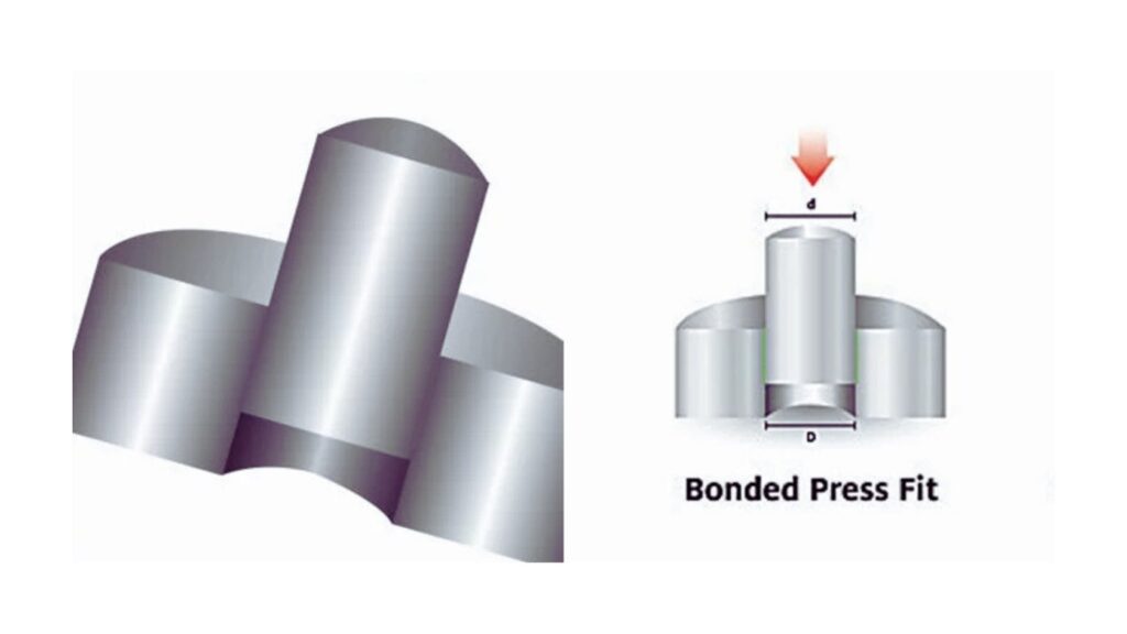
A press fit is a kind of interference fit, and it is used to assemble two parts with force. The hole is deliberately smaller than the shaft. In assembly, pressure is exerted to push the shaft in such that the materials are deformed slightly and clamp down.
This kind of fit produces a very strong bond that becomes permanent. It requires no adhesives, screws, or welds. It uses friction and tensions of the material to restrain the parts in place. The parts are once installed they cannot be moved or shifted even when under a load or vibrating.
The application of press fit would be the best when connecting gears, bearings, bushings, and also dowel pins. The fit gives strength, alignment, and resistance to movement, particularly high-performance or load-bearing assemblies.
Press Fit Design
Designing a press fit requires precision. A successful press fit must hold under load, resist vibration, and stay within tolerance. To achieve that, you need to control every step, from material choice to assembly method. These key elements will guide your design.
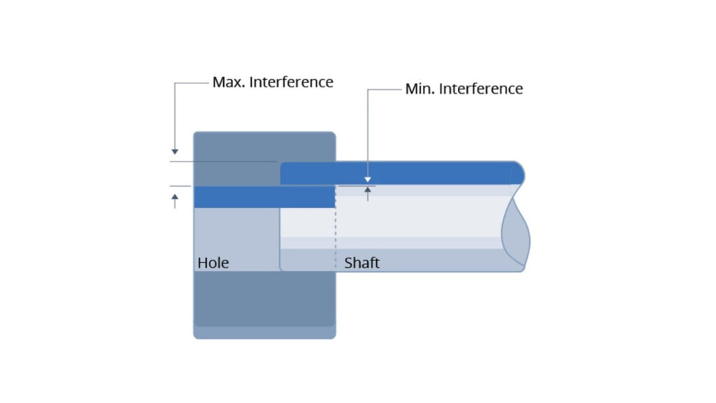
Start with your target interference. It is the difference in the hole diameter and shaft diameter. A good press fit employs interference that is controlled to lock parts.
Employ standard fit classes (e.g., ISO or ANSI classes). The hole is H7 and the shaft is m6 or n6. An example will include a 20 mm shaft having a twenty-millimeter hole that might require five to fifteen microns of interference. One must not guess-fit tolerance tables are needed here.
Small shafts require limited interference. Shafts of a large size require more. Apply hardened steel or alloys of high strength only in case your use is at a high load level or high variation in temperature.
The choice of your material does count. One component should leave a little bit because it has to be constructed. The shaft would usually be harder than the housing in order to be less damaged when pressure is absorbed.
Steel shafts are good to use along with aluminum housings. In high-load fits, steel-to-steel is not unusual, but be careful. Both components should be able to withstand pressure without too much deformation.
It is also advised that the materials used in the press fits should not be brittle, such as cast iron or ceramics. They are incapable of safe deformation, and they can crack under a load. Make sure to test the strength and elasticity of all materials so as to avoid a fit.
Press Fit Tolerance
Your pieces have to be cut in a precise manner. A press-fit can fail just by a ten-micron error. Holes may be ground or precision bored. By all means, avoid drilling without finishing reaming.
The shaft has to be circular and smoothened. Taper or out-of-round Shape will increase assembly force, as well as cause damage. With tight fittings, a roundness of less than five microns should be aimed at.
Also finish of control surface. Optimum roughness is 0.8 to 1.6 micrometers Ra. A rough surface is better as it would have more friction, but not so rough that it would tear during the assembly. A polished shaft is also important as it eases tension and sits more balanced.
Press Fit Assembly
The assembly may be mechanical or thermal. On small pieces, a manual or arbor press should be used. Make the force gradual and steady. Do not ever use a hammer-it will be the ruin of a good alignment.
Thermal expansion should be used to fit tightly or for high precision. Warm the housing to make it grow. Or cool the shaft and make it shrink. The disparity forms some space. The interference becomes locked once the temperatures get back to normal.
Apply the method that suits you depending on its level of fit. A light press fit could not require heat. Especially on shafts over fifty millimeters in diameter, a heavy press fit will.
Plip Fit Clearance
Your design should always be checked before going to production. Assemble the measures with the help of a press with load control. Compare it to the figured insertion force. The majority of fits require between two and five kilonewtons to sit properly.
Upon assembly, check the part alignment, roundness, and the damage on the surface. Retention strength can be established by pull or torque tests. In the case that the shaft has to rotate, runout should also be measured.
Measure the outcome and re-work the process when it is necessary. Excellent math can be just that, theory, since the rigid ideal in the real world can change by material batch, wear of a tool, or a setup mistake. Only test all your parameters, then lock in the final parameters.
Even the best-designed press fits may fail to perform because some important factors are not taken into consideration. Such failures are mostly due to selecting the wrong materials, incorrect interference values that are wrong, and assembly. Learning the reasons will make you avoid expensive problems in the course of production.
This occurs in cases where the housing material is brittle or too thin. When the press force is higher than the yield strength of the materials, there will be a crack during assembly or use of the part.
To avoid this, ductile materials should be used. Such materials as aluminium, mild steel, or brass permit small elastic deformation. Wall thickness should always be computed on the shaft diameter and interference. Do not use thin-wall housings unless completely supported.
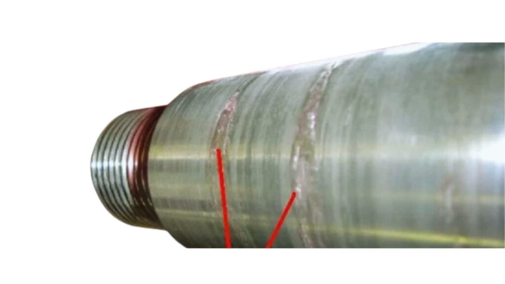
Shaft Galling
Galling is frequent during dry fits or in cases where the finishes on the surface are too rough. It brings about frictional joining of part surfaces and results in scoring or material transfer.
Avoid this by the application of an appropriate surface finish and a light press-fit lubricant. Make the finish of the shaft smoothened, usually between 0.8 to 1.6 micrometers Ra. Moreover, it is not good to reuse damaged shafts of previous fits.
When the interference is excessive, the press force required may exceed machine capabilities. This results in damage or misalignment of parts.
There are ISO fit charts to check your fit tolerances. In the case of light press fits aim at an interference between five and ten microns over twenty millimeters of diameter. Thermal fitting is also able to minimize the necessary force and decrease the stress in the assembly.
Here, this breakdown occurs when the interference becomes weak. The causes are the material creep, thermal cycling, or micro-movements under load. This ends up in the shaft loosening up in the housing.
Avoid this by assembling the matched materials having comparable thermal expansion rates. Make sure that during press-in, the surfaces have the correct contact. In life-critical applications, it may be worthwhile adding other methods of locking, such as pins or adhesives.
Misalignment in press-in translates to run out or wobble. It usually appears due to unequal pressure or a wrong setting of the tool.
Fit a preloaded press with a controlled fixture that will permit straight insertion. Do not hit or side load. Once all the parts are assembled, inspect the shaft alignment by use of a dial indicator or roundness tester.
Slip Fit
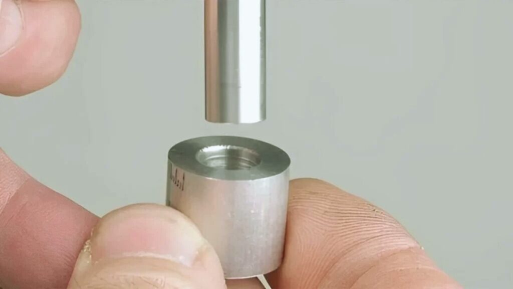
A slip fit is a type of clearance fit used to join two parts without force. The shaft is made slightly smaller than the hole. This allows the parts to slide together easily during assembly.
Slip fits are designed for smooth movement and precise alignment. The clearance is controlled to prevent friction but still guide the parts. The fit is tight enough to locate the shaft accurately, but loose enough for it to move or rotate freely.
This type of fit is ideal when the parts must be installed or removed often. It is commonly used in shafts, guide pins, bearings, and sleeves. Slip fits do not resist movement under load, so they are often paired with other locking features.
Slip fits simplify assembly, reduce wear, and allow serviceability. They are not designed to hold parts permanently. For secure holding, other fit types like press fits or fasteners are used instead.
Slip-fit design entails a trade-off between clearance, precision, and assembly. This is aimed at enabling free movement and retaining parts in position. In order to achieve repeatability, control all aspects of it- tolerances, material behavior, and finish.
Slip Fit Tolerance
Slip fits operate on the positive clearance. This implies that the shaft will never be bigger than the hole. It is not much of a difference, but an essential one. It determines the ease with which the parts slide past each other.
Use normal classes of tolerance. As an illustration, when the hole is H7 shaft may be g6 or h6. These combinations are smooth-fitting and non-loose.
There should be closer space for small parts. Bigger pieces permit some more. Refer to the check fit charts according to the diameter and purpose of the shaft.
Make use of materials with similar thermal expansion coefficients. However, when the hole is not as expanded as the shaft, the clearance might be lost when running.
In the case of a low-temperature environment, it is also advisable to use material pairs that do not contract asymmetrically. Aluminum and steel are good when it comes to moderate fits. The part behavior should always be checked under full operating conditions.
Soft material, such as plastics, can deform under a load. Where there is a possibility of such cases, provide greater clearance or a second guide feature.
Slip fits entail uniform dimensions of the part. Minor variations of machining can produce binding or looseness.
Make the hole with the use of reaming or boring. Avoid coarse drilling as well as large cutters. The shafts must have a fine grinding or turning of them. Tolerance bands should remain in a couple of microns in precision fits.
Part dimensions should be inspected by always before assembly. To verify the actual clearance, utilize plug gauges and micrometers.
Smooth surfaces eliminate friction and make clean motions. There is a chance that a rough surface can make it stick or wear. Slip fits, optimal surface roughness lies within one and two micrometers Ra.
Smooth the shaft when necessary. Do not go deep into the tool marks in either surface. In high-wear applications or in applications where high speed is involved, part life and fit behavior are directly affected by surface finish.
Slip fits may have various applications. Some get rotated. Other ones can move in a straight line or easily align.
Distinguish the motion in the initial phases of the design. In rotating shafts, vibrations can be minimized by the use of tighter fits. In the case of removable guides, looser fits are easier to dismantle.
When the fit is required to maintain the position under the load, put in set screws or retainers. Do not use the slip fit to withstand the force.
Choosing between a press fit and a slip fit depends on how the parts will function in the final assembly. Each fit offers specific benefits based on holding force, part movement, and service needs. Knowing when to use each one ensures reliable performance and efficient assembly.
The best option is press fits when you require a permanent, secure connection. They are held without fastening, gluing, or welding. This is why they are perfect in parts that are not supposed to move after assembly.
Apply in gears, bearings, pins, and rotating parts that need to be locked where press fits are used. They are also used to straighten shafts as well as to avoid axial vibrations when they are loaded. In case the part is not going to be taken out throughout its lifetime, press fit is the more appropriate option.
Slip fits are applied in cases where there is a need for the parts to slide, rotate, or be removed. They can be installed without force easily. This can be considered in assemblies that require frequent adjustment, servicing, or checking.
Slip fits are applied on guide rods, bearing housings, or on shafts where alignment is required and locking is not. They are also applied in jigs, fixtures, or in any maintenance where movement or accessories are needed.
The two types of fits need to be well-designed. Press fit accommodates the force with ease, though it should be installed with care. A slip fit is flexible, yet it does not bear loaded motion.
To choose the fit, it is worth considering the way of movement of the parts move, the way of assembly of the parts are assembled, and the amount of force the parts would be required to pass. They should always be used with the right tolerances, finish, and a match of the materials in order to get performance.
Here’s a simple comparison table for Press Fit vs Slip Fit key aspects
| Aspect | Press Fit | Slip Fit |
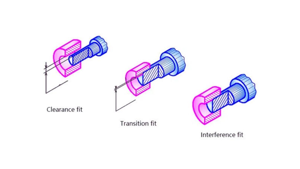
| Fit Type | Interference fit | Clearance fit |
| Assembly Force | Requires force or pressure | Fits together easily |
| Movement After Assembly | No movement (fixed) | Allows sliding or rotation |
| Typical Use | Permanent connections | Removable or adjustable parts |
| Load Resistance | High load capacity | Low load capacity |
| Disassembly | Difficult or not intended | Easy and frequent |
Press fit and slip fit serve distinct purposes in mechanical assembly. Press fits create a strong, permanent bond using interference between parts. They are ideal when parts must stay fixed under load without movement. Slip fits provide controlled clearance, allowing parts to slide or rotate easily. This makes them suitable for assemblies needing frequent removal or adjustment.
Choosing the right fit depends on the application’s functional requirements, load conditions, and service needs. Proper design involves selecting compatible materials, applying precise tolerances, and ensuring the correct surface finish. Testing and inspection validate the fit’s performance before production. Understanding these fits helps you design reliable, efficient assemblies.
What tolerance classes are typical for press fits?
Press fits often use an H7 hole combined with an M6 or n6 shaft, depending on diameter and load. These tolerances create controlled interference for a tight fit.
Can press fits be disassembled without damage?
Generally, press fits are permanent, and disassembly can damage parts. Thermal methods or specialized pullers may help, but repeated removal is not recommended.
When should I choose a slip fit over a press fit?
Choose slip fits when parts require easy assembly, movement, or removal. They work well for guide pins, bearings, and shafts that need regular maintenance or alignment.

Aluminum Heat Sinks: Process, Techniques & Applications

Aluminum Car Parts: Benefits, Techniques, and How to Source

CNC Medical Machining: Process, Techniques & Applications

Complete Automotive Machining Guide: From Discontinued Parts to Custom Solutions
Custom Automotive Parts: Methods, Challenges & Choosing the Right Manufacturer

What Is a Vacuum Casting Service? Techniques, Process, & Applications